Pcb rf interference
Understanding PCB RF Interference: Causes and Solutions
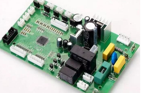
Printed Circuit Boards (PCBs) are integral components in modern electronic devices, serving as the backbone for electrical connections and signal pathways.
However, as electronic devices become more complex and operate at higher frequencies, the issue of Radio Frequency (RF) interference becomes increasingly significant.
Understanding the causes of PCB RF interference and implementing effective solutions is crucial for ensuring the optimal performance and reliability of electronic systems.
RF interference in PCBs can be attributed to several factors, including the design layout, component placement, and the materials used.
One primary cause of RF interference is the improper routing of signal traces.
When high-frequency signals are routed too closely to each other or to power and ground planes, they can induce unwanted electromagnetic coupling. This coupling can lead to crosstalk, where signals from one trace interfere with those on another, degrading signal integrity and potentially causing malfunction.
Another contributing factor is the placement of components.
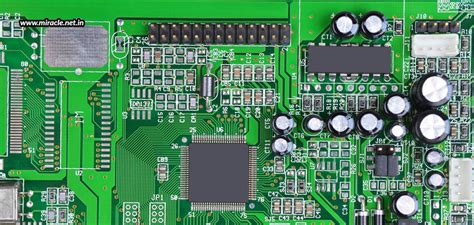
Components that emit or are susceptible to RF signals, such as oscillators, antennas, and high-speed digital circuits, should be strategically placed to minimize interference. Placing these components too close to each other or to sensitive analog circuits can exacerbate RF interference issues.
Additionally, the use of inappropriate materials for the PCB substrate can affect the board’s ability to shield against RF interference. Materials with poor dielectric properties can allow RF signals to propagate more easily, increasing the likelihood of interference.
To mitigate RF interference in PCBs, several design strategies can be employed.
One effective approach is to use proper grounding techniques. A well-designed ground plane can act as a shield, reducing the coupling of RF signals between traces. Ensuring that the ground plane is continuous and has low impedance is essential for effective shielding. Additionally, using multiple ground planes in a multilayer PCB can further enhance shielding and reduce interference.
Another important strategy is to implement proper trace routing.
High-frequency signal traces should be kept as short as possible and routed away from sensitive analog circuits. Differential signaling, where two complementary signals are routed together, can also help reduce RF interference by canceling out common-mode noise. Furthermore, the use of controlled impedance traces can ensure that signal integrity is maintained, reducing the likelihood of interference.
Component placement should also be carefully considered.
RF-emitting components should be placed away from sensitive analog circuits and shielded if necessary. Decoupling capacitors can be used to filter out high-frequency noise from power supply lines, further reducing the potential for RF interference. Additionally, the use of ferrite beads and inductors can help suppress high-frequency noise in signal and power lines.
Material selection is another critical aspect of mitigating RF interference.
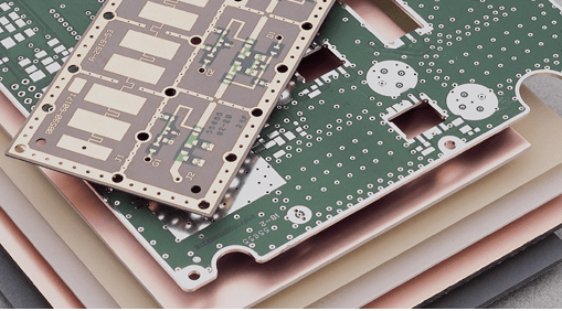
Using high-quality PCB substrates with good dielectric properties can help reduce the propagation of RF signals. Materials such as FR-4, which is commonly used in PCBs, can be effective for many applications, but for higher-frequency designs, materials with lower dielectric constants and loss tangents may be necessary.
In conclusion, understanding the causes of PCB RF interference and implementing effective solutions is essential for the reliable operation of electronic devices. By employing proper grounding techniques, trace routing, component placement, and material selection, designers can significantly reduce the impact of RF interference on their PCBs. As electronic devices continue to evolve and operate at higher frequencies, addressing RF interference will remain a critical aspect of PCB design, ensuring that devices perform optimally in increasingly complex and demanding environments.

Designing PCBs to Minimize RF Interference
Designing printed circuit boards (PCBs) to minimize radio frequency (RF) interference is a critical aspect of modern electronics engineering. As devices become more compact and complex, the potential for RF interference increases, necessitating meticulous design strategies to ensure optimal performance. RF interference can degrade the functionality of electronic devices, leading to signal loss, data corruption, and overall system unreliability. Therefore, understanding and implementing effective design principles is essential for engineers.
One of the primary considerations in minimizing RF interference is the layout of the PCB.
Proper component placement is crucial; sensitive components should be positioned away from high-frequency signal paths and noisy power supplies. Grouping components by function can also help isolate noise sources from sensitive areas. Additionally, maintaining a clear separation between analog and digital sections of the PCB can prevent cross-coupling of signals, which is a common source of interference.
Another important factor is the use of ground planes.
A continuous ground plane can significantly reduce RF interference by providing a low-impedance path for return currents. This helps to minimize the loop area, which in turn reduces the potential for electromagnetic radiation. Moreover, ground planes can act as shields, protecting sensitive components from external RF sources. It is also advisable to use multiple ground planes in multilayer PCBs to further enhance noise immunity.
Signal integrity is another critical aspect to consider.
High-speed signals should be routed with controlled impedance to prevent reflections and signal degradation. Differential signaling can be employed to reduce susceptibility to external noise and improve signal integrity. Additionally, keeping signal traces as short as possible and avoiding sharp bends can help minimize inductive and capacitive coupling, which are common sources of RF interference.
Decoupling capacitors play a vital role in mitigating RF interference.
Placing these capacitors close to power pins of integrated circuits can filter out high-frequency noise from the power supply. It is essential to choose capacitors with appropriate values and low equivalent series resistance (ESR) to ensure effective noise suppression. Furthermore, using a combination of capacitors with different values can provide a broader frequency range of noise filtering.
Shielding is another effective technique for reducing RF interference.
Enclosing sensitive components or entire sections of the PCB in metal shields can block external RF signals and prevent internal signals from radiating. However, it is important to ensure that the shields are properly grounded to avoid creating unintended antennas that could exacerbate interference issues.
In addition to these design strategies, adhering to best practices in PCB manufacturing can also help minimize RF interference.
Ensuring that the PCB is free from manufacturing defects such as incomplete solder joints or broken traces is essential for maintaining signal integrity. Regular testing and validation of the PCB design can identify potential sources of interference and allow for corrective measures to be implemented before mass production.
In conclusion, minimizing RF interference in PCB design requires a comprehensive approach that encompasses careful component placement, effective use of ground planes, attention to signal integrity, strategic use of decoupling capacitors, and appropriate shielding. By adhering to these principles, engineers can design PCBs that are robust, reliable, and capable of performing optimally in increasingly complex electronic environments. As technology continues to advance, the importance of minimizing RF interference will only grow, making these design considerations ever more critical.

Advanced Techniques for PCB RF Interference Mitigation
Printed Circuit Boards (PCBs) are the backbone of modern electronic devices, serving as the platform upon which all electronic components are mounted and interconnected. However, as devices become more complex and operate at higher frequencies, Radio Frequency (RF) interference becomes a significant concern. RF interference can degrade the performance of electronic systems, leading to data corruption, signal loss, and overall system instability. Therefore, advanced techniques for mitigating PCB RF interference are essential for ensuring the reliability and efficiency of electronic devices.
One of the primary methods for mitigating RF interference is through careful PCB layout design.
The placement of components and routing of traces can significantly impact the level of interference. For instance, keeping high-speed signal traces as short as possible can reduce the potential for RF emissions. Additionally, separating analog and digital components can minimize cross-talk and interference between different parts of the circuit. By strategically placing components and routing traces, designers can create a PCB layout that inherently reduces RF interference.
Another critical technique involves the use of ground planes.
A continuous ground plane can act as a shield, providing a low-impedance path for return currents and reducing the potential for RF emissions. Moreover, ground planes can help to isolate different sections of the PCB, further minimizing interference. It is also beneficial to use multiple ground planes in multi-layer PCBs, as this can enhance the overall shielding effectiveness. Ensuring that the ground planes are properly connected and free of discontinuities is crucial for maximizing their effectiveness in mitigating RF interference.
In addition to layout and grounding techniques, the use of decoupling capacitors is essential for RF interference mitigation.
Decoupling capacitors can filter out high-frequency noise and provide a stable power supply to the components. Placing these capacitors close to the power pins of integrated circuits can significantly reduce the potential for RF interference. Furthermore, using capacitors with different values can help to filter a broader range of frequencies, providing more comprehensive noise suppression.
Shielding is another effective method for reducing RF interference.
By enclosing sensitive components or entire sections of the PCB in a conductive shield, designers can prevent external RF signals from penetrating the circuit and internal signals from radiating out. Shielding can be implemented using metal enclosures, conductive coatings, or even specialized shielding materials. However, it is important to ensure that the shields are properly grounded to maximize their effectiveness.
Moreover, differential signaling can be employed to mitigate RF interference.
Differential signals use two complementary signals to transmit data, which can help to cancel out common-mode noise. This technique is particularly useful for high-speed data transmission, where RF interference can be a significant issue. By using differential pairs and ensuring that the traces are closely matched in length and impedance, designers can reduce the susceptibility of the circuit to RF interference.
Finally, proper termination of signal lines is crucial for minimizing RF interference.
Unterminated or improperly terminated lines can act as antennas, radiating RF energy and causing interference. Using appropriate termination techniques, such as series or parallel termination, can help to match the impedance of the signal lines and reduce reflections, thereby minimizing RF emissions.
In conclusion, mitigating PCB RF interference requires a multifaceted approach that includes careful layout design, effective grounding, the use of decoupling capacitors, shielding, differential signaling, and proper termination. By employing these advanced techniques, designers can create PCBs that are more resilient to RF interference, ensuring the reliable performance of electronic devices in increasingly complex and high-frequency environments.
The Impact of PCB Layout on RF Interference
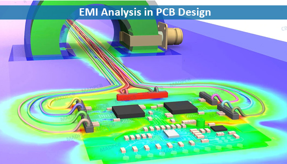
Printed Circuit Boards (PCBs) are the backbone of modern electronic devices, serving as the platform upon which all electronic components are mounted and interconnected. However, the design and layout of PCBs can significantly impact the performance of these devices, particularly in terms of Radio Frequency (RF) interference. RF interference, which can degrade the performance of electronic systems, is a critical consideration in PCB design. Understanding the relationship between PCB layout and RF interference is essential for engineers aiming to optimize the functionality and reliability of electronic devices.
To begin with, the physical layout of a PCB can influence the electromagnetic compatibility (EMC) of the device.
EMC refers to the ability of electronic equipment to function properly in its electromagnetic environment without introducing intolerable electromagnetic disturbances to anything in that environment. Poor PCB layout can lead to increased RF emissions and susceptibility, thereby compromising EMC. For instance, the placement of components, the routing of traces, and the design of power and ground planes all play pivotal roles in determining the level of RF interference.
One of the primary factors contributing to RF interference is the routing of signal traces.
Signal traces that are too long or improperly routed can act as antennas, radiating unwanted RF energy. To mitigate this, designers should aim to keep signal traces as short as possible and avoid routing them near the edges of the PCB, where they are more likely to emit RF energy. Additionally, differential signaling, which uses two complementary signals to reduce electromagnetic emissions, can be employed to further minimize RF interference.
Another crucial aspect is the placement of components.
Components that are sensitive to RF interference, such as oscillators and analog circuits, should be placed away from high-speed digital circuits and power supplies. This separation helps to reduce the coupling of RF noise between different parts of the PCB. Moreover, shielding can be used to protect sensitive components from external RF sources. Shielding involves enclosing the sensitive components in a conductive material that blocks RF energy, thereby preventing interference.
The design of power and ground planes also has a significant impact on RF interference.
A well-designed power distribution network ensures that power is delivered to all components with minimal noise. This can be achieved by using a solid ground plane, which provides a low-impedance path for return currents and helps to reduce ground loops. Ground loops, which occur when there are multiple ground paths with different potentials, can create unwanted RF emissions. By minimizing ground loops and ensuring a continuous ground plane, designers can effectively reduce RF interference.
Furthermore, decoupling capacitors are essential in mitigating RF interference.
These capacitors are placed close to the power pins of integrated circuits to filter out high-frequency noise. By providing a low-impedance path for high-frequency currents, decoupling capacitors help to stabilize the power supply and reduce RF emissions. It is important to select the appropriate value and type of decoupling capacitors to ensure optimal performance.
In conclusion, the layout of a PCB has a profound impact on RF interference, which in turn affects the overall performance and reliability of electronic devices. By carefully considering the routing of signal traces, the placement of components, the design of power and ground planes, and the use of decoupling capacitors, engineers can effectively minimize RF interference. This not only enhances the electromagnetic compatibility of the device but also ensures that it operates efficiently in its intended environment. As electronic devices continue to evolve and become more complex, the importance of meticulous PCB layout in mitigating RF interference cannot be overstated.

