PCB Salt Spray Testing: A Comprehensive Guide
1. Introduction
Printed Circuit Boards (PCBs) are essential components in modern electronics, used in everything from consumer electronics to industrial machinery and aerospace systems. Given their widespread application, ensuring the reliability and durability of PCBs under harsh environmental conditions is critical. One of the most common tests used to evaluate PCB corrosion resistance is Salt Spray Testing (also known as Salt Fog Testing).
This article provides an in-depth exploration of PCB Salt Spray Testing, including its purpose, testing standards, procedures, benefits, limitations, and best practices for improving PCB corrosion resistance.
2. What is Salt Spray Testing?
Salt Spray Testing is an accelerated corrosion test that evaluates the resistance of PCBs and other metallic components to corrosive environments. The test simulates harsh conditions, such as coastal or marine environments, where salt-laden air can cause rapid corrosion.
Key Objectives of Salt Spray Testing for PCBs:
- Assess the effectiveness of surface finishes (e.g., HASL, ENIG, OSP, Immersion Silver, etc.).
- Evaluate the performance of conformal coatings.
- Identify potential corrosion vulnerabilities in PCB materials and solder joints.
- Ensure compliance with industry standards for reliability and durability.
3. Salt Spray Testing Standards for PCBs
Several international standards govern Salt Spray Testing, ensuring consistency and reliability in test results. The most commonly referenced standards include:
A. ASTM B117 – Standard Practice for Operating Salt Spray (Fog) Apparatus
- The most widely used standard for salt spray testing.
- Specifies test conditions: 5% NaCl solution, pH 6.5-7.2, 35°C chamber temperature.
- Defines exposure durations (typically 24 to 1000+ hours).
B. IEC 60068-2-11 (Test Ka: Salt Mist)
- Used for electrical and electronic components.
- Similar to ASTM B117 but includes additional pass/fail criteria.
C. ISO 9227 – Corrosion Tests in Artificial Atmospheres – Salt Spray Tests
- An international standard with variations for neutral (NSS), acetic acid (AASS), and copper-accelerated (CASS) salt spray tests.
D. IPC-TM-650 (Test Method 2.6.11)
- Specific to PCB testing.
- Evaluates surface insulation resistance (SIR) after salt spray exposure.
4. PCB Salt Spray Testing Procedure
The Salt Spray Testing process involves several key steps:
A. Sample Preparation
- Clean PCBs to remove contaminants.
- Apply conformal coatings (if testing coated boards).
- Mask areas not intended for exposure (e.g., connectors).
B. Test Chamber Setup
- Fill the chamber with a 5% NaCl solution.
- Maintain a constant temperature (35°C ± 2°C).
- Adjust pH to 6.5-7.2 (neutral salt spray) or modify for acidic/copper-accelerated tests.
C. Exposure Duration
- Typical durations: 24h, 48h, 96h, 168h, 500h, or 1000h.
- Longer exposures simulate more severe conditions.
D. Post-Test Evaluation
- Visual inspection for corrosion, blistering, or delamination.
- Electrical testing (continuity, insulation resistance).
- Cross-sectional analysis (if needed).
5. Factors Affecting PCB Corrosion in Salt Spray Testing
Several factors influence PCB performance in salt spray tests:
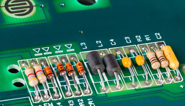
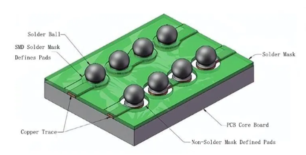
A. PCB Surface Finish
- HASL (Hot Air Solder Leveling): Prone to corrosion due to exposed copper.
- ENIG (Electroless Nickel Immersion Gold): Excellent corrosion resistance.
- OSP (Organic Solderability Preservative): Limited protection; degrades quickly.
- Immersion Silver/Tin: Moderate resistance but susceptible to creep corrosion.
B. Conformal Coating
- Acrylic, silicone, polyurethane, and epoxy coatings enhance protection.
- Poor coating application (pinholes, thin spots) leads to failure.
C. PCB Material Selection
- FR-4 is standard but may absorb moisture.
- High-Tg or halogen-free materials offer better resistance.
D. Design Considerations
- Traces too close to edges increase corrosion risk.
- Poor solder mask adhesion accelerates degradation.
6. Benefits of Salt Spray Testing for PCBs
- Accelerated Corrosion Assessment: Simulates years of exposure in weeks.
- Quality Control: Identifies manufacturing defects early.
- Comparative Analysis: Helps select the best surface finishes and coatings.
- Regulatory Compliance: Meets industry and military standards.
7. Limitations of Salt Spray Test
8. Improving PCB Resistance to Salt Spray Corrosion
To enhance PCB durability, consider:
A. Optimal Surface Finishes
- Use ENIG or ENEPIG for high-reliability applications.
- Avoid bare copper in harsh environments.
B. Effective Conformal Coating
- Apply silicone or polyurethane coatings for maximum protection.
- Ensure uniform thickness (25-75 μm recommended).
C. Robust PCB Design
- Increase solder mask coverage.
- Avoid sharp edges and exposed copper.
D. Material Upgrades
9. Alternative Corrosion Tests for PCBs
Since Salt Spray Testing has limitations, complementary tests include:
- Humidity Testing (85°C/85% RH)
- Thermal Cycling
- Mixed Flowing Gas (MFG) Testing
- Electrochemical Impedance Spectroscopy (EIS)
10. Conclusion
Salt Spray Testing is a critical tool for evaluating PCB corrosion resistance, helping manufacturers ensure product reliability in harsh environments. While it has limitations, combining it with other environmental tests provides a comprehensive durability assessment.
By selecting appropriate surface finishes, conformal coatings, and materials, PCB designers and manufacturers can significantly improve corrosion resistance, extending the lifespan of electronic devices in demanding applications.
For industries such as automotive, aerospace, marine, and industrial electronics, rigorous salt spray testing is indispensable for delivering high-quality, long-lasting PCBs.