Pcb soldering
Techniques For Soldering Surface-Mount Components
Soldering surface-mount components (SMCs) onto printed circuit boards (PCBs) is a critical skill in modern electronics manufacturing. This technique requires precision and a thorough understanding of the materials and tools involved. To achieve optimal results, it is essential to follow a series of well-defined steps and employ specific techniques that ensure the reliability and functionality of the final product.
Initially, the preparation of the PCB and components is paramount.
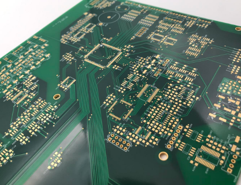
The PCB should be clean and free of any contaminants that could interfere with the soldering process. This can be achieved by using isopropyl alcohol and a lint-free cloth to remove any dust, oils, or residues. Similarly, the surface-mount components should be inspected for any defects or damage before proceeding.
Once the PCB and components are prepared, the next step involves applying solder paste to the PCB pads.
Solder paste is a mixture of tiny solder balls and flux, which helps in the soldering process by cleaning the metal surfaces and improving the flow of solder. The application of solder paste can be done using a stencil, which ensures that the paste is applied accurately and uniformly to the designated areas. This step is crucial as it directly impacts the quality of the solder joints.
After the solder paste has been applied, the surface-mount components are placed onto the PCB.
This requires precision and care, as improper placement can lead to poor connections or short circuits. Tools such as tweezers or vacuum pick-up tools are commonly used to handle the small components. It is important to ensure that each component is correctly oriented and aligned with the corresponding pads on the PCB.
With the components in place, the next phase involves the reflow soldering process.
This technique uses controlled heat to melt the solder paste, creating a strong bond between the components and the PCB. Reflow soldering can be performed using a reflow oven, which provides a consistent and controlled heating profile. The PCB is passed through the oven, where it is gradually heated to the melting point of the solder paste and then cooled to solidify the connections. It is essential to follow the recommended temperature profile for the specific solder paste being used to avoid damaging the components or the PCB.
In some cases, manual soldering may be required, especially for rework or repair tasks.
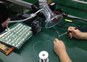
This involves using a soldering iron with a fine tip to apply solder directly to the component leads and PCB pads. The key to successful manual soldering is maintaining the correct temperature and using the appropriate amount of solder. Excessive heat can damage the components, while insufficient heat can result in weak or unreliable connections. Additionally, using flux can help improve the flow of solder and ensure a clean, strong joint.
Finally, after the soldering process is complete, it is important to inspect the PCB for any defects or issues.
This can be done visually or using tools such as magnifying glasses or microscopes. Common issues to look for include solder bridges, cold joints, and misaligned components. Any defects should be addressed promptly to ensure the functionality and reliability of the PCB.
In conclusion, soldering surface-mount components onto PCBs requires careful preparation, precise application of solder paste, accurate component placement, and controlled heating during the reflow process. By following these techniques and paying attention to detail, high-quality and reliable solder joints can be achieved, ensuring the optimal performance of the final electronic product.
Common Mistakes To Avoid In PCB Soldering
PCB soldering is a critical process in the assembly of electronic devices, requiring precision and attention to detail. However, even experienced technicians can fall prey to common mistakes that can compromise the integrity and functionality of the final product. One prevalent error is the use of excessive solder. While it might seem that more solder would ensure a stronger connection, it can actually lead to bridging, where solder unintentionally connects adjacent pads or traces, causing short circuits. To avoid this, it is essential to apply just enough solder to form a reliable joint without creating excess that could spread to other components.
Another frequent mistake is insufficient heating.
Proper soldering requires the joint to be heated adequately to allow the solder to flow and bond correctly. If the soldering iron is not hot enough or if it is not applied for a sufficient duration, the solder may not melt properly, resulting in a cold joint. Cold joints are characterized by a dull, grainy appearance and are prone to failure. Ensuring that the soldering iron is at the correct temperature and maintaining contact with the joint for the appropriate amount of time can mitigate this issue.
In addition to temperature control, the cleanliness of the components and the PCB itself is paramount.
Contaminants such as oils, dust, and oxidation can prevent proper solder adhesion, leading to weak joints. Therefore, it is crucial to clean the surfaces with isopropyl alcohol or a specialized PCB cleaner before soldering. This step removes any residues that could interfere with the soldering process, ensuring a strong and reliable connection.
Moreover, the choice of solder and flux plays a significant role in the quality of the solder joints.
Using the wrong type of solder or flux can result in poor wetting, where the solder does not spread evenly over the joint. Lead-free solders, for instance, require higher temperatures and different flux formulations compared to traditional lead-based solders. Understanding the specific requirements of the materials being used and selecting the appropriate solder and flux can prevent issues related to poor wetting and ensure a robust connection.
Another aspect to consider is the handling of components during the soldering process.
Excessive force or improper handling can damage delicate components or the PCB itself. For example, applying too much pressure with the soldering iron can lift pads from the PCB, rendering the board unusable. Using tools such as tweezers and ensuring a gentle touch can help avoid such damage.
Furthermore, it is important to be mindful of the duration for which heat is applied to the components.
Prolonged exposure to high temperatures can damage sensitive components, leading to thermal stress and potential failure. Using a temperature-controlled soldering iron and working efficiently can help minimize the risk of heat damage.
Lastly, inspecting the solder joints after completion is a crucial step that should not be overlooked.
Visual inspection can reveal issues such as cold joints, bridging, and insufficient solder. Additionally, using tools like magnifying glasses or microscopes can help identify defects that are not visible to the naked eye. Addressing these issues promptly can prevent future failures and ensure the reliability of the electronic device.
In conclusion, avoiding common mistakes in PCB soldering requires a combination of proper technique, appropriate materials, and careful handling. By paying attention to details such as solder quantity, heating, cleanliness, material selection, component handling, and inspection, technicians can achieve high-quality solder joints that contribute to the overall reliability and performance of electronic devices.

Essential Tools For Effective PCB Soldering
Printed Circuit Board (PCB) soldering is a critical process in the assembly and repair of electronic devices. To achieve effective and reliable soldering, it is essential to utilize the right tools. The selection of appropriate tools not only ensures precision and efficiency but also minimizes the risk of damaging sensitive components. Therefore, understanding the essential tools for PCB soldering is paramount for both novice and experienced technicians.
First and foremost, a high-quality soldering iron is indispensable.
The soldering iron is the primary tool used to melt solder and create electrical connections between components and the PCB. It is advisable to choose a soldering iron with adjustable temperature control, as different soldering tasks may require varying temperatures. Additionally, a soldering iron with a fine tip is preferable for working on intricate and densely populated PCBs, allowing for greater precision and control.
In conjunction with the soldering iron, solder is another fundamental material.
Solder is typically composed of a mixture of tin and lead, although lead-free alternatives are increasingly popular due to health and environmental concerns. The choice of solder should be guided by the specific requirements of the project, including the melting point and the type of flux core. Flux is a chemical agent that facilitates the soldering process by cleaning and preparing the metal surfaces, thereby ensuring a strong and reliable bond.
Moreover, a soldering station can significantly enhance the soldering experience.
A soldering station usually includes a soldering iron, a stand, and a temperature control unit. The stand provides a safe place to rest the hot soldering iron when not in use, reducing the risk of accidental burns or damage to the work surface. The temperature control unit allows for precise adjustments, ensuring that the soldering iron operates at the optimal temperature for the task at hand.
To complement the soldering iron and solder, a set of tweezers is essential for handling small components.
Tweezers enable technicians to place and hold components accurately while soldering, which is particularly important when working with surface-mount technology (SMT) components. Additionally, tweezers can be used to remove excess solder or to reposition components during the soldering process.
Another crucial tool is the desoldering pump, also known as a solder sucker.
This tool is used to remove unwanted solder from a joint, which is particularly useful during repair work or when correcting mistakes. The desoldering pump creates a vacuum that quickly and efficiently extracts molten solder, allowing for the clean removal of components.
Furthermore, a magnifying glass or microscope is invaluable for inspecting solder joints and ensuring their quality.
Given the small size of many electronic components, visual inspection with the naked eye may not be sufficient. A magnifying tool allows for a detailed examination of the solder joints, helping to identify any defects such as cold joints, bridges, or insufficient solder coverage.
In addition to these primary tools, several auxiliary tools can further enhance the soldering process.
For instance, a spool of solder wick, also known as desoldering braid, can be used to absorb excess solder from a joint. A set of small wire cutters and pliers is useful for trimming component leads and manipulating wires. Additionally, a heat-resistant mat can protect the work surface from damage caused by the high temperatures involved in soldering.
In conclusion, effective PCB soldering requires a combination of essential tools, each serving a specific purpose in the process. By investing in high-quality tools such as a soldering iron with adjustable temperature control, appropriate solder, a soldering station, tweezers, a desoldering pump, and magnifying tools, technicians can ensure precision, efficiency, and reliability in their soldering work. These tools, when used correctly, contribute to the successful assembly and repair of electronic devices, ultimately enhancing the performance and longevity of the final product.
Step-By-Step Guide To Hand Soldering Through-Hole Components
Hand soldering through-hole components onto a printed circuit board (PCB) is a fundamental skill in electronics assembly, requiring precision and attention to detail. To begin, gather all necessary tools and materials, including a soldering iron, solder, flux, a PCB, and the through-hole components. Ensuring a clean and organized workspace is crucial for efficient and effective soldering.
First, prepare the PCB by inspecting it for any defects or debris.
Clean the board with isopropyl alcohol to remove any contaminants that could affect soldering quality. Next, identify the locations where the components will be placed, referring to the schematic or layout diagram. This step is essential to avoid errors during assembly.
Once the PCB is ready, proceed to prepare the components.
Bend the leads of the through-hole components to fit the designated holes on the PCB. Insert the components into their respective positions, ensuring that they are seated flush against the board. It is advisable to insert and solder one component at a time to maintain control and accuracy.
With the components in place, turn the PCB over to access the leads protruding through the holes.
Secure the board in a vise or a third-hand tool to keep it stable during soldering. Before applying solder, it is beneficial to apply a small amount of flux to the leads and pads. Flux helps to clean the metal surfaces and improve the flow of solder, resulting in stronger and more reliable joints.
Heat the soldering iron to the appropriate temperature, typically around 350°C (662°F) for most soldering tasks.
Touch the tip of the soldering iron to both the lead and the pad simultaneously, heating them for a few seconds. Then, introduce the solder to the joint, allowing it to flow and cover the connection. Remove the soldering iron and solder once a shiny, concave fillet forms around the lead and pad. This indicates a good solder joint.
Repeat this process for each component, taking care to avoid overheating the components or the PCB.
Overheating can damage sensitive components and cause the PCB to delaminate. If a joint appears dull or has not formed correctly, reheat it and apply a small amount of additional solder.
After all components are soldered, inspect the joints for quality. A good solder joint should be smooth, shiny, and free of voids or excess solder. Use a magnifying glass to check for any cold joints, which appear grainy and may not provide a reliable electrical connection. If any defects are found, rework the joints as necessary.
Finally, trim the excess leads using flush cutters, being careful not to damage the solder joints or the PCB. Clean the board again with isopropyl alcohol to remove any residual flux, which can be corrosive over time. This step ensures the longevity and reliability of the assembled PCB.
In conclusion, hand soldering through-hole components onto a PCB requires careful preparation, precise technique, and thorough inspection. By following these steps, one can achieve high-quality solder joints that ensure the proper functioning of the electronic assembly. Mastery of this skill is essential for anyone involved in electronics, from hobbyists to professional engineers.