Pcb stackup for high speed
Understanding PCB Stackup Design for High-Speed Applications
In the realm of high-speed electronic applications, the design of printed circuit boards (PCBs) plays a pivotal role in ensuring optimal performance and reliability. One of the most critical aspects of PCB design is the stackup configuration, which refers to the arrangement of conductive and insulating layers within the board. Understanding the intricacies of PCB stackup design is essential for engineers and designers aiming to meet the demanding requirements of high-speed applications.
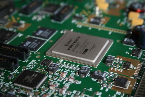
To begin with, the primary objective of a PCB stackup is to minimize electromagnetic interference (EMI) and signal integrity issues, which are prevalent in high-speed circuits. By carefully selecting the number and order of layers, designers can control the impedance and crosstalk, thereby enhancing the overall performance of the PCB. Typically, a high-speed PCB stackup consists of multiple layers, including signal layers, power planes, and ground planes. The arrangement of these layers is crucial, as it directly impacts the electrical characteristics of the board.
One of the fundamental principles in designing a PCB stackup for high-speed applications is the use of ground planes.
Ground planes serve as a reference point for signals and help in reducing EMI by providing a return path for current. Placing ground planes adjacent to signal layers is a common practice, as it helps in maintaining signal integrity by minimizing the loop area and reducing inductance. Moreover, having continuous ground planes across the board ensures a uniform distribution of return currents, which is vital for high-speed signal transmission.
In addition to ground planes, power planes are equally important in a high-speed PCB stackup.
Power planes provide a stable voltage reference and help in reducing power supply noise. By placing power planes close to ground planes, designers can create a decoupling effect, which minimizes voltage fluctuations and enhances the power integrity of the board. This proximity also aids in reducing the loop inductance, which is crucial for maintaining signal integrity at high frequencies.
Another critical consideration in PCB stackup design is the selection of materials.
The dielectric material used between layers significantly affects the electrical performance of the board. For high-speed applications, materials with low dielectric constant and low loss tangent are preferred, as they reduce signal attenuation and dispersion. Additionally, the thickness of the dielectric layers should be carefully chosen to achieve the desired impedance levels, which is essential for matching the impedance of transmission lines and minimizing reflections.
Furthermore, the arrangement of signal layers within the stackup is a key factor in controlling crosstalk and ensuring signal integrity.
By strategically placing high-speed signal layers between ground planes, designers can create a shielding effect that reduces electromagnetic coupling between adjacent traces. This configuration, often referred to as a stripline or microstrip structure, is effective in minimizing crosstalk and maintaining signal quality.
In conclusion, designing a PCB stackup for high-speed applications requires a comprehensive understanding of electromagnetic principles and careful consideration of various factors, including layer arrangement, material selection, and impedance control. By optimizing these elements, engineers can create PCBs that meet the stringent demands of high-speed circuits, ensuring reliable and efficient performance. As technology continues to advance, the importance of meticulous PCB stackup design will only grow, underscoring its critical role in the development of cutting-edge electronic systems.
Key Considerations in High-Speed PCB Stackup Layering
In the realm of high-speed electronics, the design of printed circuit boards (PCBs) plays a pivotal role in ensuring optimal performance and reliability. One of the most critical aspects of PCB design is the stackup configuration, which involves the arrangement of various layers within the board. This configuration is particularly crucial for high-speed applications, where signal integrity, electromagnetic interference (EMI), and thermal management are of paramount importance. Understanding the key considerations in high-speed PCB stackup layering can significantly enhance the performance of electronic devices.
To begin with, the selection of materials is a fundamental consideration in high-speed PCB stackup design.
The dielectric material used between the layers must have a low loss tangent and a consistent dielectric constant to minimize signal degradation. Materials such as FR-4, while commonly used, may not always be suitable for high-speed applications due to their higher loss characteristics. Instead, advanced materials like Rogers or Taconic, which offer better high-frequency performance, are often preferred. The choice of material directly impacts the impedance control and signal propagation speed, making it a critical decision in the stackup design process.
Moreover, the arrangement of signal and power layers within the stackup is another vital consideration.
A well-designed stackup typically alternates between signal and plane layers, which helps in reducing crosstalk and maintaining signal integrity. Placing power and ground planes adjacent to each other can create a low-inductance path, which is beneficial for high-speed signal return paths. This configuration also aids in effective power distribution and minimizes voltage fluctuations, thereby enhancing the overall performance of the PCB.
In addition to material selection and layer arrangement, the aspect of impedance control cannot be overlooked.
Impedance mismatches can lead to signal reflections, which degrade signal quality and can cause data errors. To achieve controlled impedance, careful attention must be paid to the trace width, spacing, and the dielectric thickness between layers. Simulation tools are often employed to model and predict impedance characteristics, allowing designers to make informed decisions and adjustments during the design phase.
Furthermore, thermal management is a critical consideration in high-speed PCB stackup design.
High-speed circuits often generate significant amounts of heat, which can adversely affect performance and reliability if not properly managed. Incorporating thermal vias, heat sinks, and appropriate copper thickness can help dissipate heat effectively. Additionally, selecting materials with good thermal conductivity can further enhance heat dissipation, ensuring that the PCB operates within safe temperature limits.
Transitioning to the topic of electromagnetic interference, it is essential to consider EMI shielding in the stackup design.
High-speed signals can radiate electromagnetic energy, potentially interfering with other components or systems. To mitigate EMI, designers can incorporate ground planes and use differential signaling techniques. Additionally, maintaining a compact and symmetrical stackup can help reduce loop areas, thereby minimizing EMI emissions.
In conclusion, the design of a high-speed PCB stackup involves a careful balance of material selection, layer arrangement, impedance control, thermal management, and EMI considerations. Each of these factors plays a crucial role in ensuring that the PCB can handle high-speed signals effectively while maintaining signal integrity and reliability. By understanding and addressing these key considerations, designers can create PCBs that meet the demanding requirements of modern high-speed electronic applications.
Material Selection for High-Speed PCB Stackup Optimization
In the realm of high-speed printed circuit board (PCB) design, the selection of materials for stackup optimization is a critical factor that can significantly influence the performance and reliability of the final product. As electronic devices continue to evolve, demanding faster data rates and higher frequencies, the need for meticulous material selection becomes increasingly paramount. The choice of materials not only affects the electrical performance but also impacts the thermal and mechanical properties of the PCB, which are crucial for maintaining signal integrity and ensuring long-term durability.
To begin with, understanding the dielectric properties of materials is essential for high-speed PCB stackup optimization.
Dielectric constant (Dk) and dissipation factor (Df) are two key parameters that influence signal propagation speed and loss. Materials with a low Dk are preferred for high-speed applications as they allow signals to travel faster, reducing the potential for signal delay. Similarly, a low Df is desirable to minimize signal loss, which is particularly important at higher frequencies where losses can be more pronounced. Consequently, materials such as polytetrafluoroethylene (PTFE) and certain ceramic-filled laminates are often chosen for their favorable dielectric properties.
Moreover, the thermal management capabilities of the materials cannot be overlooked.
High-speed circuits generate significant heat, and inadequate thermal management can lead to performance degradation or even failure. Therefore, materials with high thermal conductivity are advantageous as they facilitate efficient heat dissipation. Additionally, the coefficient of thermal expansion (CTE) should be considered to ensure compatibility with other components and to prevent mechanical stress during thermal cycling. Materials that exhibit a low CTE, such as certain advanced composites, are often preferred to maintain structural integrity and alignment.
Transitioning to the mechanical aspects, the rigidity and flexibility of the materials play a vital role in the overall reliability of the PCB.
High-speed applications often require a balance between rigidity for support and flexibility for accommodating design constraints. Materials that offer a good compromise, such as certain high-performance epoxy resins, are frequently utilized to achieve this balance. Furthermore, the choice of copper foil type and thickness is another critical consideration. Thinner copper layers can reduce skin effect losses at high frequencies, while the surface roughness of the copper can impact signal integrity. Therefore, selecting copper foils with smooth surfaces is beneficial for minimizing signal distortion.
In addition to these technical considerations, cost and availability are practical factors that influence material selection.
While high-performance materials can offer superior electrical and thermal properties, they often come at a higher cost. Designers must weigh the benefits against the budget constraints and availability of materials. It is essential to collaborate with material suppliers to ensure that the chosen materials can be sourced reliably and within the project timeline.
In conclusion, the optimization of high-speed PCB stackup through careful material selection is a multifaceted process that requires a comprehensive understanding of electrical, thermal, and mechanical properties. By considering factors such as dielectric properties, thermal management, mechanical stability, and practical constraints, designers can enhance the performance and reliability of high-speed PCBs. As technology continues to advance, the importance of informed material selection will only grow, underscoring its role as a cornerstone of successful high-speed PCB design.
Signal Integrity Challenges in High-Speed PCB Stackup Design
In the realm of high-speed printed circuit board (PCB) design, signal integrity emerges as a critical concern, necessitating meticulous attention to the PCB stackup. As electronic devices continue to evolve, demanding faster data rates and higher performance, the challenges associated with maintaining signal integrity become increasingly complex. The PCB stackup, which refers to the arrangement of conductive and insulating layers within a PCB, plays a pivotal role in mitigating these challenges. Understanding the intricacies of stackup design is essential for engineers striving to optimize signal integrity in high-speed applications.
To begin with, the choice of materials in a PCB stackup significantly influences signal integrity.
High-speed signals are susceptible to losses and distortions as they traverse the PCB, and these effects are exacerbated by the dielectric properties of the materials used. Low-loss dielectric materials are preferred in high-speed designs to minimize signal attenuation and maintain signal fidelity. Furthermore, the thickness of these materials must be carefully controlled to ensure consistent impedance, which is crucial for reducing reflections and maintaining signal quality.
Transitioning to the arrangement of layers, the stackup configuration directly impacts the electromagnetic compatibility and crosstalk between signals.
A well-designed stackup strategically places power and ground planes to provide effective return paths for high-speed signals, thereby reducing electromagnetic interference (EMI). By sandwiching signal layers between ground planes, designers can create a controlled impedance environment that minimizes crosstalk and enhances signal integrity. This configuration not only aids in maintaining signal quality but also contributes to the overall reliability of the PCB.
Moreover, the aspect of impedance control cannot be overstated in high-speed PCB stackup design.
Impedance mismatches can lead to signal reflections, which degrade signal integrity and can cause data errors. To address this, designers must carefully calculate and control the trace widths and spacing, as well as the dielectric thickness, to achieve the desired impedance levels. This requires a comprehensive understanding of the electrical properties of the materials and the geometric parameters of the stackup.
In addition to material selection and layer arrangement, the aspect of via design is another critical factor influencing signal integrity in high-speed PCBs.
Vias, which are used to connect different layers of a PCB, can introduce unwanted inductance and capacitance, leading to signal degradation. To mitigate these effects, designers often employ techniques such as back-drilling to remove unused via stubs, thereby reducing parasitic effects. Additionally, the use of blind and buried vias can help minimize the impact on signal integrity by reducing the number of layer transitions.
As we delve deeper into the nuances of high-speed PCB stackup design, it becomes evident that a holistic approach is necessary to address signal integrity challenges.
This involves not only optimizing the stackup configuration but also considering factors such as trace routing, termination techniques, and power distribution. By adopting a comprehensive design strategy, engineers can effectively manage the complexities associated with high-speed signals and ensure robust performance.
In conclusion, the design of a PCB stackup for high-speed applications is a multifaceted endeavor that demands careful consideration of material properties, layer arrangement, impedance control, and via design. By addressing these elements with precision, engineers can overcome signal integrity challenges and pave the way for the successful implementation of high-speed electronic systems. As technology continues to advance, the importance of mastering PCB stackup design will only grow, underscoring its critical role in the future of high-speed electronics.


