PCB Technology: Ceramic Capacitors vs. Electrolytic Capacitors
Introduction
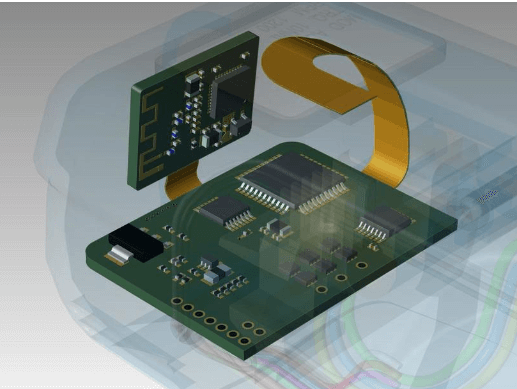
Printed Circuit Boards (PCBs) are the backbone of modern electronics, integrating various components to ensure optimal functionality. Among these components, capacitors play a crucial role in filtering, decoupling, energy storage, and signal conditioning. Two of the most commonly used capacitors in PCB design are ceramic capacitors and electrolytic capacitors. While both serve similar fundamental purposes, they differ significantly in construction, performance, and application suitability.
This article explores the key differences between ceramic and electrolytic capacitors, their advantages and disadvantages, and their optimal use cases in PCB technology.
1. Ceramic Capacitors
1.1 Construction and Working Principle
Ceramic capacitors are non-polarized components made using ceramic materials as the dielectric. They consist of alternating layers of ceramic and metal electrodes, which are then sintered at high temperatures to form a compact structure.
- Dielectric Material: Typically made from barium titanate or other ceramic compounds.
- Electrodes: Silver, palladium, or nickel.
- Packaging: Available in surface-mount (SMD) configurations such as 0402, 0603, and 0805, as well as through-hole variants.
1.2 Types of Ceramic Capacitors
Ceramic capacitors are classified based on their dielectric properties:
- Class 1 (NP0/C0G): High stability, low losses, and minimal capacitance variation with temperature. Ideal for resonant circuits and RF applications.
- Class 2 (X7R, X5R, Y5V): Higher capacitance values but less stable with temperature and voltage. Used in decoupling and filtering applications.
1.3 Advantages
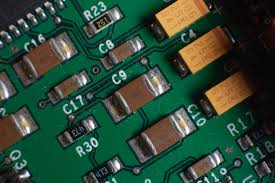
- Small size and high capacitance density (especially in multilayer ceramic capacitors, MLCCs).
- Low Equivalent Series Resistance (ESR) and Equivalent Series Inductance (ESL).
- No polarity, making them easy to implement in circuits.
- Long lifespan with no electrolyte drying issues.
- Excellent high-frequency performance, making them ideal for decoupling in digital circuits.
1.4 Disadvantages
- Capacitance decreases with DC bias voltage (especially in Class 2 dielectrics).
- Piezoelectric effects can cause audible noise in some circuits.
- Limited maximum capacitance (typically up to a few hundred µF).
1.5 Common Applications
- Decoupling and bypassing in high-speed digital circuits (CPUs, GPUs).
- RF and microwave circuits due to low parasitic effects.
- Timing circuits where stability is critical.
2. Electrolytic Capacitors
2.1 Construction and Working Principle
Electrolytic capacitors are polarized components that use an electrolyte (liquid or solid) to achieve high capacitance values. They are divided into two main types:
- Aluminum Electrolytic Capacitors: Use an aluminum oxide dielectric and a liquid or gel electrolyte.
- Tantalum Electrolytic Capacitors: Use tantalum pentoxide as the dielectric and a solid or liquid electrolyte.
2.2 Key Characteristics
- High capacitance-to-volume ratio (up to thousands of µF).
- Polarity-sensitive (reverse voltage can cause failure).
- Higher ESR and ESL compared to ceramic capacitors.
2.3 Advantages
- High capacitance values (from µF to mF range), suitable for power supply filtering.
- Cost-effective for bulk capacitance needs.
- Available in both through-hole and SMD packages.
2.4 Disadvantages
- Limited lifespan due to electrolyte drying (especially in aluminum electrolytics).
- Higher ESR and ESL, leading to poorer high-frequency performance.
- Sensitive to temperature and voltage spikes.
- Tantalum capacitors can fail catastrophically if subjected to overvoltage or reverse bias.
2.5 Common Applications
- Power supply filtering and smoothing (e.g., in AC-DC converters).
- Audio circuits (coupling and decoupling).
- Energy storage in low-frequency applications.
3. Ceramic vs. Electrolytic Capacitors: Key Comparisons
| Parameter | Ceramic Capacitors | Electrolytic Capacitors |
|---|---|---|
| Polarity | Non-polarized | Polarized |
| Capacitance Range | pF to ~100 µF | µF to mF |
| ESR/ESL | Very low | Higher |
| Lifespan | Very long | Limited (electrolyte drying) |
| Temperature Stability | Excellent (Class 1) | Moderate |
| Voltage Sensitivity | Capacitance drops with DC bias | Can fail under reverse voltage |
| Cost | Moderate (MLCCs can be expensive) | Low to moderate |
| High-Frequency Performance | Excellent | Poor |
4. Choosing the Right Capacitor for PCB Design
4.1 When to Use Ceramic Capacitors
- High-frequency decoupling (e.g., near IC power pins).
- Precision timing circuits (e.g., oscillators).
- Miniaturized designs where space is limited.
4.2 When to Use Electrolytic Capacitors
- Power supply bulk capacitance (e.g., smoothing rectified AC).
- Low-frequency energy storage (e.g., audio amplifiers).
- Cost-sensitive applications requiring high capacitance.
4.3 Hybrid Approaches
Many modern PCBs use a combination of both:
- Ceramic capacitors for high-frequency noise suppression.
- Electrolytic capacitors for bulk energy storage.
5. Future Trends in Capacitor Technology
- Advanced MLCCs with higher capacitance and lower DC bias effects.
- Polymer electrolytic capacitors offering longer lifespans and lower ESR.
- Supercapacitors bridging the gap between traditional capacitors and batteries.
6. Conclusion
Both ceramic and electrolytic capacitors are indispensable in PCB technology, each excelling in different applications. Ceramic capacitors dominate high-frequency, compact, and precision circuits, while electrolytic capacitors are preferred for high-capacitance, low-frequency power applications.
Understanding their differences allows engineers to optimize PCB designs for performance, reliability, and cost. As capacitor technology evolves, new materials and designs will further enhance their roles in next-generation electronics.