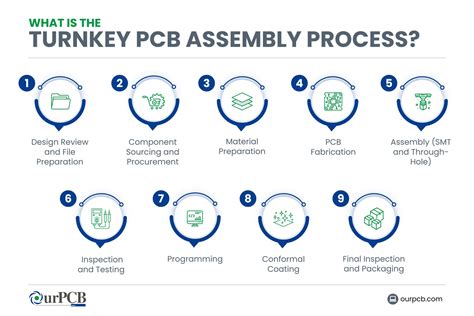
PCB Testing: Electromagnetic Components
Testing PCB electromagnetic components is a key aspect of PCB testing. So, what are the methods for testing PCB electromagnetic components?
1.General Coil Testing
For coil testing, you can use a digital bridge to measure inductance online. Since inductors often operate at high frequencies, you can set the frequency to 10kHz or higher for testing.
2.Transformer Coil Testing
By measuring the inductance D of the transformer’s main winding, you can determine if there is a short circuit between turns. To do this, set the digital bridge to 0.3V or lower and 10kHz or higher, and measure the main winding’s inductance D. If D is greater than 0.1, the transformer is considered damaged and unusable.
3.Hall Effect Device Testing
Hall Effect sensors are available with single or dual power supplies, and with current and voltage outputs. For single-power sensors, when no current is detected, the output signal is generally half that of the single-power supply. If the signal output deviates significantly from the midpoint at zero current, quantitative testing of the sensor can also be performed to determine if the Hall Effect sensor is damaged. A dual-power Hall effect sensor outputs zero voltage when sensing zero current. When sensing non-zero current, the output voltage’s sign and magnitude change depending on the magnitude and direction of the induced current.
4.Relay Testing
Common relay faults include coil breakage, contact failure, high contact resistance, and burnt contacts. The best way to test a relay is to power it on, applying the rated voltage to the coil and then testing the contacts for continuity.