PCB Thermal Management: Techniques, Challenges, and Best Practices
1. Introduction
Printed Circuit Boards (PCBs) are the backbone of modern electronic devices, supporting complex circuits and high-power components. As electronic systems become more compact and powerful, managing heat dissipation has become a critical challenge. Excessive heat can degrade performance, reduce component lifespan, and even lead to catastrophic failures. Therefore, effective PCB thermal management is essential for ensuring reliability, efficiency, and longevity in electronic designs.
This article explores the fundamentals of PCB thermal management, common heat generation sources, thermal analysis techniques, and effective cooling strategies. We will also discuss advanced materials and emerging trends in thermal management.
2. Heat Generation in PCBs
Heat in PCBs is primarily generated by:
2.1 Power Components
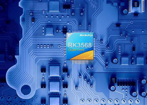
- Processors & Microcontrollers: High-speed CPUs and GPUs generate significant heat due to switching losses.
- Power Regulators & Converters: Linear regulators and switching converters (e.g., buck/boost) dissipate heat due to inefficiencies.
- RF & High-Frequency Circuits: Amplifiers and transceivers produce heat due to signal losses.
2.2 Passive Components
- Resistors: Dissipate heat proportional to ( I^2R ) losses.
- Inductors & Transformers: Core and copper losses contribute to heating.
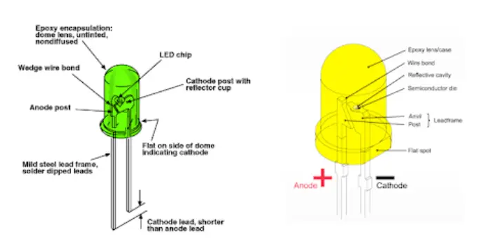
- Diodes & Transistors: Forward voltage drops and switching losses generate heat.
2.3 Trace Resistance
- High-current traces (( I^2R ) losses) can become significant heat sources, especially in power electronics.
3. Thermal Analysis Techniques
To optimize PCB thermal performance, engineers use several analysis methods:
3.1 Thermal Simulation (Finite Element Analysis – FEA)
- Software tools like ANSYS Icepak, COMSOL, and SolidWorks Flow Simulation simulate heat distribution.
- Helps identify hotspots and optimize component placement.
3.2 Infrared Thermography
- Non-contact measurement using IR cameras to detect temperature variations.
- Useful for prototype validation.
3.3 Thermal Resistance Calculations
- Junction-to-ambient thermal resistance (( \theta_{JA} )) estimates component temperature rise.
- PCB material thermal conductivity (( k )) affects heat spreading.
3.4 Computational Fluid Dynamics (CFD)
- Simulates airflow and cooling efficiency in enclosures.

4. PCB Thermal Management Techniques
Several strategies help mitigate heat buildup in PCBs:
4.1 PCB Material Selection
- FR-4 vs. High-Tg Materials: Standard FR-4 has low thermal conductivity (~0.3 W/mK), while metal-core PCBs (e.g., aluminum, copper) offer better heat dissipation.
- Ceramic & Thermal Substrates: Alumina (Al₂O₃) and aluminum nitride (AlN) provide superior thermal performance.
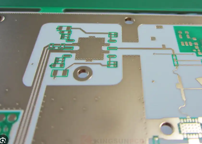
4.2 Copper Pour & Thermal Vias
- Copper Planes: Large copper areas act as heat spreaders.
- Thermal Vias: Plated holes transfer heat from top to bottom layers, improving conduction.
4.3 Heat Sinks & Thermal Interface Materials (TIMs)
- Heat Sinks: Attached to high-power components (e.g., MOSFETs, processors) to enhance convection cooling.
- TIMs (Thermal Pads, Pastes, Adhesives): Improve heat transfer between components and heat sinks.
4.4 Active Cooling Solutions
- Fans & Blowers: Force airflow over critical components.
- Liquid Cooling: Used in high-power applications (e.g., servers, electric vehicles).
4.5 Component Layout Optimization
- Spacing High-Power Components: Prevents localized overheating.
- Thermal Relief Pads: Reduces soldering heat impact while maintaining conductivity.
4.6 Enclosure Design & Ventilation
- Natural Convection: Vents and heat-dissipating enclosures improve passive cooling.
- Forced Airflow: Strategically placed fans enhance cooling efficiency.
5. Advanced Thermal Management Solutions
Emerging technologies are pushing the boundaries of PCB cooling:
5.1 Embedded Cooling Channels
- Microfluidic channels integrated into PCBs for liquid cooling (used in high-performance computing).
5.2 Phase Change Materials (PCMs)
- Absorb and release heat during phase transitions (e.g., wax-based materials).
5.3 Graphene & Carbon-Based Materials
- Exceptional thermal conductivity (~5000 W/mK) for next-gen PCBs.
5.4 3D-Printed Heat Exchangers
- Custom-designed heat sinks optimized for specific thermal profiles.
6. Challenges in PCB Thermal Management
Despite advancements, several challenges persist:
6.1 Miniaturization & High Power Density
- Smaller devices generate more heat in confined spaces.
6.2 Cost vs. Performance Trade-offs
- High-performance thermal solutions (e.g., liquid cooling) increase manufacturing costs.
6.3 Reliability Under Thermal Cycling
- Repeated heating/cooling cycles cause solder joint fatigue and delamination.
6.4 Environmental Considerations
- Harsh environments (e.g., automotive, aerospace) demand robust thermal solutions.
7. Best Practices for Effective Thermal Management
To ensure optimal thermal performance:
- Simulate Early: Use thermal analysis tools during the design phase.
- Optimize Layout: Place high-power components strategically.
- Use Thermal Vias & Copper Pour: Enhance heat spreading.
- Select Appropriate Materials: Consider metal-core or high-thermal-conductivity substrates.
- Test Prototypes: Validate thermal performance with IR thermography.
- Monitor In-Field Performance: Use temperature sensors for real-time thermal management.
8. Conclusion
Effective PCB thermal management is crucial for modern electronics, where power densities continue to rise. By leveraging simulation tools, advanced materials, and innovative cooling techniques, engineers can mitigate thermal issues and enhance device reliability. As technology evolves, emerging solutions like embedded liquid cooling and graphene-based materials will play a pivotal role in shaping the future of thermal management in PCBs.
By adopting a proactive approach—integrating thermal considerations early in the design process—engineers can ensure that electronic systems remain efficient, durable, and safe under demanding operating conditions.