PCB Welding Defects: Causes, Types, and Prevention Strategies
Introduction to PCB Welding Defects
Printed Circuit Board (PCB) welding is a critical process in electronics manufacturing that directly impacts product quality, reliability, and performance. Welding defects in PCBs can lead to intermittent connections, complete circuit failures, or reduced product lifespan. As electronic devices become more complex and miniaturized, the challenges in maintaining high-quality solder joints have increased significantly.
PCB welding defects occur during the soldering process when components are attached to the board. These defects can stem from various factors including improper soldering techniques, material incompatibilities, design flaws, or environmental conditions. Understanding these defects is essential for quality control engineers, manufacturing professionals, and electronics designers who aim to produce reliable electronic products.
The consequences of PCB welding defects can range from minor performance issues to catastrophic failures, especially in critical applications like medical devices, aerospace electronics, or automotive systems. This article provides a comprehensive examination of common PCB welding defects, their root causes, detection methods, and effective prevention strategies.
Common Types of PCB Welding Defects
1. Cold Solder Joints
Cold solder joints are among the most prevalent welding defects in PCB assembly. They occur when the solder fails to melt completely or properly flow onto the pad and component lead. This results in a dull, grainy appearance rather than the characteristic smooth, shiny surface of a proper solder joint.
The primary causes of cold solder joints include:
- Insufficient heat during the soldering process
- Contaminated surfaces (oxidation, dirt, or grease)
- Improper soldering iron temperature
- Excessive movement of components before solder solidification
Cold solder joints create unreliable electrical connections that may work intermittently or fail completely under mechanical stress or thermal cycling. They are particularly problematic in high-vibration environments or applications with frequent temperature fluctuations.
2. Solder Bridges
Solder bridges occur when excess solder creates an unintended connection between two or more adjacent pins or pads. This defect is especially common in fine-pitch components and surface-mount technology (SMT) assemblies.
Key factors contributing to solder bridging:
- Excessive solder application
- Improper pad design (insufficient spacing)
- Incorrect solder mask alignment
- Inappropriate solder paste stencil thickness
- Component misalignment during placement
Solder bridges can cause short circuits between different circuit paths, leading to malfunction or complete failure of the electronic device. They are particularly problematic in high-density interconnect (HDI) PCBs where space between conductors is minimal.
3. Tombstoning (Component Lifting)
Tombstoning, also known as the Manhattan effect or drawbridging, occurs when one end of a surface-mount component lifts from the PCB pad during reflow soldering, standing vertically like a tombstone.
This defect primarily affects small passive components like resistors and capacitors and is caused by:
- Uneven heating of component terminals
- Imbalanced pad sizes for the component ends
- Uneven solder paste deposition
- Mismatched thermal mass between component ends
- Excessive temperature gradients during reflow
Tombstoning results in an open circuit since one end of the component isn’t properly connected to the PCB. The defect is easily visible during visual inspection but can be challenging to prevent without careful process control.
4. Solder Balling
Solder balling refers to the formation of small spherical solder particles scattered around solder joints or on the PCB surface. These balls can cause short circuits if they bridge between conductors.
Common causes include:
- Excessive solder paste application
- Poor quality or oxidized solder paste
- Improper reflow profile (especially ramp rate)
- Contamination on PCB surfaces
- Moisture absorption in solder paste
Solder balls are particularly problematic in high-frequency circuits where they can affect signal integrity, even if they don’t create direct shorts.
5. Insufficient Solder (Weak Joints)
Insufficient solder results in weak mechanical and electrical connections that may fail under stress. These joints lack adequate solder to form a proper fillet between the component lead and PCB pad.
Contributing factors:
- Inadequate solder paste deposition
- Poor wetting of surfaces
- Component lead or PCB pad oxidation
- Incorrect soldering iron tip size or temperature
- Insufficient flux activity
Weak joints are prone to cracking under thermal or mechanical stress and often show higher electrical resistance than proper solder joints.
6. Pad Lifting
Pad lifting occurs when the copper pad separates from the PCB substrate during soldering or subsequent handling. This severe defect often requires board repair or replacement.
Primary causes:
- Excessive thermal or mechanical stress during soldering
- Poor adhesion between copper and substrate
- Multiple rework cycles on the same pad
- Improper handling with excessive force
Pad lifting is particularly common in single-layer boards or those with poor thermal management, where localized overheating can weaken the adhesive bond.
Root Causes of PCB Welding Defects
Understanding the fundamental causes of PCB welding defects is essential for developing effective prevention strategies. These causes can be categorized into several main areas:
1. Process-Related Factors
The soldering process itself is a primary source of potential defects. Key process factors include:
Temperature Control: Improper temperature profiles during reflow or wave soldering can lead to various defects. Too low temperatures cause cold joints, while excessive heat can damage components or lift pads.
Time Parameters: Dwell time in wave soldering or time above liquidus in reflow soldering must be carefully controlled. Insufficient time prevents proper joint formation, while excessive time can lead to intermetallic growth or component damage.
Equipment Maintenance: Poorly maintained soldering equipment with oxidized tips, inconsistent temperature control, or worn mechanical parts contributes to defect formation.
2. Material-Related Factors
The quality and compatibility of materials used in PCB assembly significantly affect soldering outcomes:
Solder Alloy Composition: The choice of solder alloy (e.g., Sn-Pb, SAC305, etc.) affects wetting behavior, melting temperature, and joint reliability. Impurities in solder can lead to poor joint quality.
Flux Activity: The type and activity level of flux must match the application. Inactive flux fails to properly clean surfaces, while overly aggressive flux may cause corrosion.
PCB Surface Finish: Different surface finishes (HASL, ENIG, OSP, etc.) have varying solderability characteristics that affect joint formation.
Component Terminations: The plating material and quality of component leads affect their ability to form reliable solder joints.
3. Design-Related Factors
PCB design decisions can predispose the assembly to certain welding defects:
Pad Geometry: Improperly sized or shaped pads can lead to tombstoning, insufficient solder, or bridging.
Component Placement: Dense component placement increases the risk of bridging and makes rework more difficult.
Thermal Considerations: Uneven thermal mass distribution across the board can create localized temperature variations during soldering.
4. Environmental Factors
The manufacturing environment plays a role in soldering quality:
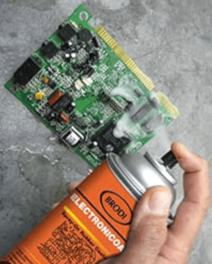
Cleanliness: Dust, grease, or other contaminants on PCB surfaces impair solderability.
Humidity: Moisture can cause solder splattering or affect solder paste performance.
Static Control: Electrostatic discharge can damage components during handling.
Detection and Inspection Methods
Identifying PCB welding defects requires a combination of inspection techniques:
1. Visual Inspection
Basic visual examination, often aided by magnification, can detect many obvious defects like bridging, tombstoning, or gross insufficient solder. Automated Optical Inspection (AOI) systems provide consistent, high-speed visual examination of solder joints.
2. X-Ray Inspection
For hidden joints like BGA (Ball Grid Array) connections, x-ray inspection is essential. This method reveals voids, insufficient solder, or alignment issues not visible from the surface.
3. Automated Testing
Electrical testing methods include:
- In-Circuit Testing (ICT) checks individual component functionality
- Flying Probe testing verifies electrical connectivity
- Boundary Scan testing examines digital circuit interconnections
4. Thermal Imaging
Infrared cameras can identify poor thermal connections or uneven heat distribution that may indicate defective solder joints.
Prevention and Mitigation Strategies
1. Process Optimization
- Develop and maintain precise temperature profiles for all soldering processes
- Implement strict process control measures and regular equipment maintenance
- Establish proper handling procedures to prevent contamination
- Conduct regular process audits and capability studies
2. Design for Manufacturing (DFM)
- Follow industry standards for pad sizes and spacing
- Consider thermal mass distribution in layout
- Provide adequate clearance for rework and inspection
- Select appropriate materials and finishes for the application
3. Material Control
- Implement proper solder paste storage and handling procedures
- Monitor solder bath composition in wave soldering
- Use components with appropriate termination finishes
- Control inventory to prevent use of expired materials
4. Operator Training
- Provide comprehensive training on soldering techniques
- Establish certification programs for critical operations
- Foster defect awareness and problem-solving skills
- Encourage continuous improvement mindset
5. Quality Systems
- Implement statistical process control (SPC) for key parameters
- Maintain thorough documentation of processes and changes
- Establish traceability systems for materials and production
- Conduct regular failure analysis and corrective actions
Emerging Trends in PCB Welding Quality
The electronics industry continues to evolve, presenting new challenges and solutions for PCB welding quality:
Advanced Materials: New solder alloys with improved thermal and mechanical properties are being developed, especially for lead-free applications requiring higher reliability.
Miniaturization: As components shrink to 01005 size and below, new soldering techniques and inspection methods are required to maintain quality.
3D Printing: Additive manufacturing techniques for electronics may revolutionize PCB production and component attachment methods.
AI in Inspection: Machine learning algorithms are increasingly being applied to automate defect detection and classification in AOI and x-ray systems.
IoT Monitoring: Real-time process monitoring using IoT sensors enables immediate detection of process deviations that could lead to defects.
Conclusion
PCB welding defects represent a significant challenge in electronics manufacturing, with potential impacts on product quality, reliability, and cost. By understanding the various types of defects, their root causes, and effective prevention strategies, manufacturers can significantly improve their production yields and product performance.
The most effective approach to minimizing welding defects combines proper design, material selection, process control, and operator training. As electronic devices continue to evolve, staying informed about new soldering technologies and inspection methods will be essential for maintaining high-quality standards.
Implementing robust quality systems, conducting regular process audits, and fostering a culture of continuous improvement will help organizations reduce PCB welding defects and deliver more reliable electronic products to market. The investment in defect prevention ultimately pays dividends through reduced rework costs, improved customer satisfaction, and enhanced brand reputation in competitive electronics markets.