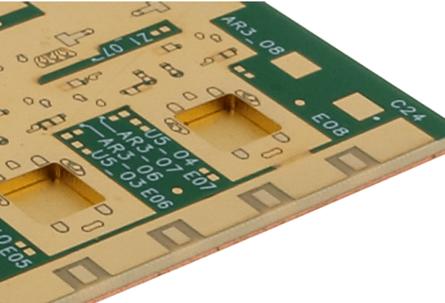
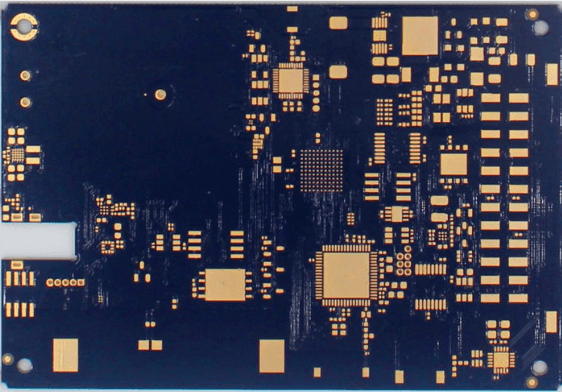
Rf and high speed pcb and emi design fundamentals
Understanding Rf and high speed pcb and emi design fundamentals
In the realm of high-speed printed circuit board (PCB) design, understanding radio frequency (RF) signal integrity is paramount. As electronic devices continue to evolve, the demand for faster data transmission rates and higher frequencies has surged, making RF signal integrity a critical consideration. Ensuring that signals maintain their integrity as they traverse the PCB is essential for the reliable performance of modern electronic systems.
To begin with, RF signal integrity refers to the preservation of the quality and fidelity of RF signals as they propagate through a PCB.
This involves minimizing signal degradation, which can be caused by various factors such as impedance mismatches, crosstalk, and electromagnetic interference (EMI). Impedance mismatches occur when there is a discontinuity in the transmission line, leading to signal reflections that can distort the original signal. To mitigate this, designers must carefully control the impedance of traces by considering factors such as trace width, spacing, and the dielectric properties of the PCB material.
Moreover, crosstalk, which is the unwanted coupling of signals between adjacent traces, poses a significant challenge in high-speed PCB design.
Crosstalk can lead to signal distortion and data corruption, particularly in densely packed PCBs. To address this, designers can employ techniques such as increasing the spacing between traces, using differential signaling, and incorporating ground planes to provide a return path for signals and reduce coupling.
In addition to impedance mismatches and crosstalk, EMI is another critical factor that can adversely affect RF signal integrity.
EMI can originate from both external sources, such as nearby electronic devices, and internal sources, such as switching power supplies and high-speed digital circuits. To mitigate EMI, designers can implement shielding techniques, such as using ground planes and metal enclosures, to isolate sensitive RF circuits from potential sources of interference. Additionally, proper grounding and decoupling strategies can help minimize EMI by providing a low-impedance path for high-frequency noise to return to the ground.
Transitioning to the layout considerations, the physical arrangement of components and traces on a PCB plays a crucial role in maintaining RF signal integrity.
For instance, placing high-speed components close to each other can reduce the length of signal paths, thereby minimizing signal degradation. Furthermore, the use of controlled impedance traces, which are designed to have a specific impedance value, can help ensure consistent signal transmission and reduce reflections.
Another important aspect of RF signal integrity is the selection of appropriate PCB materials.
The dielectric constant and loss tangent of the PCB material can significantly impact signal propagation. Low-loss materials, such as Rogers or Teflon, are often preferred for high-frequency applications as they exhibit lower signal attenuation and better performance at higher frequencies compared to standard FR-4 materials.
Furthermore, the use of simulation tools can greatly aid in the design process by allowing designers to model and analyze the behavior of RF signals on the PCB.
These tools can help identify potential issues such as impedance mismatches, crosstalk, and EMI, enabling designers to make informed decisions and optimize the PCB layout for improved signal integrity.
In conclusion, understanding RF signal integrity in high-speed PCB design is essential for ensuring the reliable performance of modern electronic systems. By addressing factors such as impedance mismatches, crosstalk, and EMI, and by carefully considering layout and material choices, designers can effectively preserve the quality of RF signals. As technology continues to advance, the importance of maintaining RF signal integrity will only grow, making it a critical area of focus for PCB designers.
Essential Techniques for Minimizing EMI in PCB Layouts
Electromagnetic interference (EMI) is a critical concern in the design of high-speed printed circuit boards (PCBs) and radio frequency (RF) circuits. Effective EMI management is essential to ensure the reliable operation of electronic devices, as it can significantly impact signal integrity and overall system performance. To minimize EMI in PCB layouts, several essential techniques must be employed, each contributing to the reduction of unwanted electromagnetic emissions and susceptibility.
One of the fundamental techniques for minimizing EMI is the careful design of the PCB layout.
This begins with the strategic placement of components. High-speed and RF components should be positioned to minimize the length of signal traces, thereby reducing the potential for radiated emissions. Additionally, sensitive analog components should be isolated from noisy digital components to prevent interference. By grouping similar types of components together and maintaining adequate spacing between them, designers can effectively manage EMI.
Another crucial aspect of EMI reduction is the use of proper grounding techniques.
A solid ground plane is indispensable in high-speed and RF PCB designs. It provides a low-impedance path for return currents, which helps to minimize ground loops and reduce EMI. Ensuring that the ground plane is continuous and unbroken is vital, as any gaps or discontinuities can create potential EMI sources. Furthermore, the use of multiple ground planes in multilayer PCBs can enhance EMI performance by providing additional shielding and reducing the inductance of return paths.
In addition to grounding, the routing of signal traces plays a significant role in EMI management.
Differential signaling is a preferred method for high-speed data transmission, as it helps to cancel out common-mode noise and reduce EMI. When routing differential pairs, it is essential to maintain consistent trace spacing and length matching to ensure signal integrity. For single-ended signals, keeping traces as short as possible and avoiding sharp bends can help minimize EMI. Moreover, routing high-speed signals on internal layers, sandwiched between ground planes, can provide additional shielding and reduce radiated emissions.
The use of decoupling capacitors is another effective technique for minimizing EMI.
These capacitors are placed close to power pins of integrated circuits (ICs) to filter out high-frequency noise and provide a stable power supply. Selecting the appropriate value and type of decoupling capacitors is crucial, as different capacitors are effective at different frequency ranges. Additionally, placing multiple capacitors with varying values in parallel can provide a broader frequency coverage and enhance EMI suppression.
Shielding is also an important consideration in EMI management.
Metal enclosures or shields can be used to contain and isolate high-frequency components, preventing them from radiating EMI. When designing shields, it is essential to ensure proper grounding and to avoid creating gaps or openings that could allow EMI to escape. Furthermore, the use of ferrite beads and chokes on signal and power lines can help to filter out high-frequency noise and reduce EMI.
Finally, adhering to design guidelines and standards is essential for effective EMI management.
Industry standards, such as those set by the International Electrotechnical Commission (IEC) and the Federal Communications Commission (FCC), provide valuable guidance on EMI reduction techniques and testing procedures. By following these standards, designers can ensure that their PCB layouts meet regulatory requirements and perform reliably in real-world applications.
In conclusion, minimizing EMI in PCB layouts requires a comprehensive approach that encompasses component placement, grounding, signal routing, decoupling, shielding, and adherence to industry standards. By employing these essential techniques, designers can effectively manage EMI, ensuring the reliable operation and performance of high-speed and RF circuits.
Best Practices for High-Speed PCB Routing to Reduce Signal Loss
When designing high-speed printed circuit boards (PCBs), minimizing signal loss is paramount to ensuring optimal performance and reliability. Signal integrity can be compromised by various factors, including impedance mismatches, crosstalk, and electromagnetic interference (EMI). Therefore, adhering to best practices in high-speed PCB routing is essential to mitigate these issues and maintain signal fidelity.
One of the fundamental principles in high-speed PCB design is maintaining controlled impedance.
Controlled impedance ensures that the signal traces have a consistent impedance, which is crucial for minimizing reflections and signal loss. To achieve this, designers must carefully select the trace width, spacing, and the dielectric material of the PCB. Utilizing impedance calculators and simulation tools can aid in determining the appropriate parameters for the specific design requirements.
In addition to controlled impedance, proper trace routing is critical.
High-speed signals should be routed with minimal bends and corners, as sharp angles can cause signal reflections and degrade signal quality. When bends are necessary, using 45-degree angles instead of 90-degree angles can help reduce impedance discontinuities. Furthermore, keeping trace lengths as short as possible is advisable to minimize signal attenuation and delay.
Another best practice is the use of differential pairs for high-speed signals.
Differential signaling involves transmitting signals over two complementary traces, which helps to reduce susceptibility to EMI and crosstalk. When routing differential pairs, it is essential to maintain consistent spacing between the traces to ensure balanced impedance and signal integrity. Additionally, the length of the differential pairs should be matched to prevent skew, which can lead to timing issues.
Ground planes play a crucial role in high-speed PCB design by providing a low-impedance return path for signals and reducing EMI.
A continuous ground plane beneath high-speed signal traces can help to minimize signal loss and crosstalk. It is also important to avoid splitting ground planes, as this can create impedance discontinuities and increase the risk of EMI. When multiple ground planes are necessary, they should be connected with vias to ensure a low-impedance path.
Decoupling capacitors are another essential component in high-speed PCB design.
These capacitors help to filter out noise and provide a stable power supply to the components. Placing decoupling capacitors close to the power pins of integrated circuits (ICs) can help to reduce power supply noise and improve signal integrity. Additionally, using a combination of capacitors with different values can provide effective filtering across a wide range of frequencies.
Signal integrity can also be enhanced by careful layer stack-up design.
A well-designed layer stack-up can help to control impedance, reduce crosstalk, and improve EMI performance. Typically, high-speed signal layers should be adjacent to ground or power planes to provide a low-impedance return path. Additionally, separating high-speed signal layers with ground or power planes can help to reduce crosstalk between adjacent signal layers.
Finally, simulation and testing are indispensable in high-speed PCB design.
Simulation tools can help to identify potential signal integrity issues and optimize the design before fabrication. Post-fabrication testing, such as time-domain reflectometry (TDR) and signal integrity analysis, can verify that the PCB meets the design specifications and performs as expected.
In conclusion, adhering to best practices in high-speed PCB routing is essential for reducing signal loss and ensuring reliable performance. By maintaining controlled impedance, proper trace routing, using differential pairs, incorporating ground planes, placing decoupling capacitors strategically, designing an effective layer stack-up, and utilizing simulation and testing, designers can achieve optimal signal integrity and minimize the impact of EMI. These practices are fundamental to the successful design of high-speed PCBs in today’s increasingly complex and demanding electronic environments.
Key Considerations for RF Shielding in PCB Design
In the realm of RF and high-speed PCB design, effective RF shielding is paramount to ensure optimal performance and mitigate electromagnetic interference (EMI). As electronic devices become increasingly complex and operate at higher frequencies, the need for robust RF shielding becomes even more critical. To achieve this, several key considerations must be taken into account during the design process.
Firstly, understanding the sources of EMI is essential.
EMI can originate from both internal and external sources, including other components on the PCB, adjacent electronic devices, and environmental factors. Identifying these sources early in the design phase allows for strategic placement of shielding materials and components to minimize interference. For instance, placing sensitive components away from high-frequency signal paths can significantly reduce the risk of EMI.
Moreover, the choice of materials plays a crucial role in RF shielding.
Conductive materials such as copper, aluminum, and specialized shielding fabrics are commonly used to create barriers that block or attenuate electromagnetic waves. The effectiveness of these materials depends on their conductivity, permeability, and thickness. Therefore, selecting the appropriate material based on the specific frequency range and environmental conditions is vital for achieving optimal shielding performance.
In addition to material selection, the design of the PCB layout itself is a critical factor.
Proper grounding techniques are essential to create a low-impedance path for unwanted signals to dissipate. This can be achieved by implementing a solid ground plane, which provides a continuous conductive surface that helps to shield sensitive components and reduce EMI. Furthermore, ensuring that the ground plane is properly connected to the chassis ground can enhance the overall shielding effectiveness.
Another important consideration is the use of shielding enclosures.
These enclosures, often made of metal, surround the entire PCB or specific sections of it to provide a physical barrier against EMI. When designing these enclosures, it is important to consider factors such as ventilation, accessibility, and thermal management. Proper ventilation ensures that the components do not overheat, while accessibility allows for easy maintenance and troubleshooting. Thermal management, on the other hand, involves designing the enclosure in a way that dissipates heat effectively, preventing thermal buildup that could affect the performance of the PCB.
Furthermore, the implementation of filtering techniques can significantly enhance RF shielding.
Filters such as capacitors, inductors, and ferrite beads can be used to block or attenuate unwanted high-frequency signals. These components are typically placed at strategic points in the circuit, such as power supply lines and signal traces, to prevent EMI from propagating through the PCB. By carefully selecting and placing these filters, designers can effectively reduce the impact of EMI on the overall performance of the PCB.
Lastly, it is important to consider the impact of PCB design on signal integrity.
High-speed signals are particularly susceptible to EMI, which can cause signal degradation and data loss. To mitigate this, designers should focus on minimizing signal reflections and crosstalk by carefully routing signal traces and maintaining consistent impedance. Techniques such as differential signaling and controlled impedance routing can help to preserve signal integrity and reduce the risk of EMI.
In conclusion, effective RF shielding in PCB design requires a comprehensive approach that considers various factors, including the identification of EMI sources, material selection, PCB layout, shielding enclosures, filtering techniques, and signal integrity. By addressing these key considerations, designers can create robust and reliable PCBs that perform optimally in high-frequency and high-speed applications.


