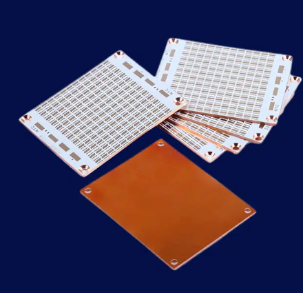
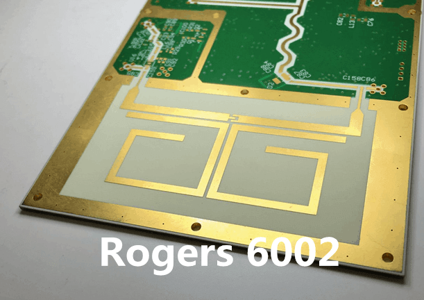
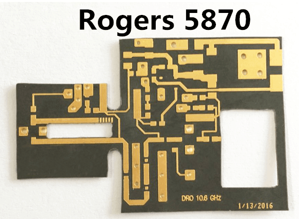
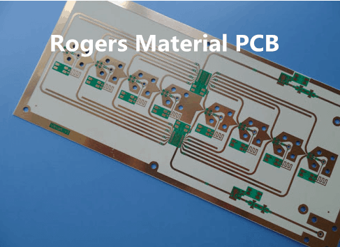
Rf pcb material rogers
Advantages Of Using Rf pcb material rogers
Rogers materials have become a cornerstone in the design and manufacturing of Radio Frequency (RF) Printed Circuit Boards (PCBs), offering a multitude of advantages that make them highly sought after in the industry.
One of the primary benefits of using Rogers material in RF PCB design is its exceptional dielectric properties.
These materials exhibit low dielectric constant (Dk) and low dissipation factor (Df), which are crucial for maintaining signal integrity and minimizing signal loss at high frequencies. This ensures that the performance of RF circuits remains consistent and reliable, even in demanding applications.
Moreover, Rogers materials are known for their excellent thermal management capabilities.
In RF applications, where components often generate significant heat, effective thermal management is essential to prevent overheating and ensure the longevity of the PCB. Rogers materials possess high thermal conductivity, which allows for efficient heat dissipation, thereby enhancing the overall performance and reliability of the RF PCB. This is particularly important in applications such as telecommunications, aerospace, and defense, where maintaining optimal operating temperatures is critical.
In addition to their superior electrical and thermal properties, Rogers materials offer outstanding mechanical stability.
They exhibit low thermal expansion, which means that they maintain their dimensional stability even under varying temperature conditions. This is a significant advantage in RF PCB design, as it ensures that the physical dimensions of the board remain consistent, preventing issues such as misalignment and mechanical stress that could compromise the performance of the circuit. Furthermore, the mechanical robustness of Rogers materials makes them suitable for use in harsh environments, where they can withstand mechanical shocks and vibrations without degrading.
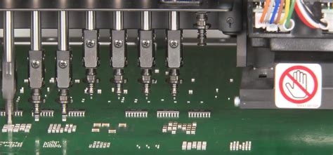
Another notable advantage of using Rogers material in RF PCB design is its ease of fabrication.
These materials are compatible with standard PCB manufacturing processes, which simplifies the production process and reduces costs. The consistency and uniformity of Rogers materials also contribute to higher yield rates, as they minimize the occurrence of defects and variations during manufacturing. This is particularly beneficial for high-volume production, where maintaining quality and consistency is paramount.
Furthermore, Rogers materials are available in a wide range of formulations, allowing designers to select the most appropriate material for their specific application requirements.
This versatility enables the optimization of RF PCB performance by tailoring the material properties to match the desired electrical, thermal, and mechanical characteristics. For instance, designers can choose materials with specific dielectric constants to achieve the desired impedance control, or select materials with enhanced thermal conductivity for applications with high power dissipation.
In conclusion, the advantages of using Rogers material in RF PCB design are manifold. Their exceptional dielectric properties ensure signal integrity and minimize loss, while their excellent thermal management capabilities enhance performance and reliability. The mechanical stability of Rogers materials ensures dimensional consistency and robustness in harsh environments, and their ease of fabrication simplifies the manufacturing process and reduces costs. The versatility of Rogers materials allows for the optimization of RF PCB performance by tailoring material properties to specific application requirements. These benefits collectively make Rogers materials an ideal choice for RF PCB design, enabling the development of high-performance, reliable, and cost-effective solutions for a wide range of applications.
Comparing Rogers RF PCB Material To Other Substrates
When selecting materials for radio frequency (RF) printed circuit boards (PCBs), engineers and designers often face a critical decision that can significantly impact the performance and reliability of their designs. Among the various options available, Rogers RF PCB materials have garnered considerable attention due to their unique properties and advantages. To fully appreciate the benefits of Rogers materials, it is essential to compare them with other commonly used substrates in RF applications.
One of the primary considerations in choosing an RF PCB material is its dielectric constant (Dk).
The dielectric constant affects signal speed and impedance, which are crucial for maintaining signal integrity in high-frequency applications. Rogers materials, such as the popular RO4000 series, offer a low and stable dielectric constant, typically ranging from 3.38 to 3.55. This stability across a wide frequency range ensures consistent performance, which is particularly important in applications like telecommunications and radar systems. In contrast, traditional FR-4 materials, commonly used in standard PCBs, have a higher and less stable dielectric constant, often around 4.5. This variability can lead to signal distortion and impedance mismatches, making FR-4 less suitable for high-frequency applications.
Another critical factor is the loss tangent, which measures the energy loss of a signal as it propagates through the material.
Lower loss tangents are desirable for minimizing signal attenuation and maintaining signal strength over longer distances. Rogers materials are known for their low loss tangents, with values typically below 0.0037 at 10 GHz. This low loss characteristic makes Rogers substrates ideal for high-frequency and high-speed applications, where signal integrity is paramount. In comparison, FR-4 materials exhibit higher loss tangents, often around 0.02 at 10 GHz, resulting in greater signal loss and reduced performance in RF applications.
Thermal management is another area where Rogers materials excel.
High-frequency circuits often generate significant heat, and effective thermal management is crucial to prevent overheating and ensure reliable operation. Rogers materials, such as the RO3000 series, offer excellent thermal conductivity, which helps dissipate heat more efficiently than many other substrates. This property is particularly beneficial in power amplifiers and other high-power RF applications. On the other hand, FR-4 materials have lower thermal conductivity, which can lead to heat buildup and potential failure in high-power scenarios.
Mechanical stability and ease of fabrication are also important considerations.
Rogers materials are designed to offer excellent dimensional stability, even under varying environmental conditions. This stability ensures that the physical dimensions of the PCB remain consistent, which is critical for maintaining precise signal paths and impedance control. Additionally, Rogers materials are compatible with standard PCB manufacturing processes, making them relatively easy to work with. In contrast, some alternative high-frequency materials may require specialized fabrication techniques, increasing production complexity and cost.
Cost is often a significant factor in material selection.
While Rogers materials tend to be more expensive than FR-4, their superior performance characteristics can justify the higher cost in many high-frequency applications. The improved signal integrity, reduced signal loss, and better thermal management provided by Rogers substrates can lead to more reliable and efficient designs, ultimately resulting in cost savings through enhanced performance and reduced need for rework or redesign.
In conclusion, when comparing Rogers RF PCB materials to other substrates, it becomes evident that Rogers offers distinct advantages in terms of dielectric constant stability, low loss tangent, thermal management, mechanical stability, and ease of fabrication. While the initial cost may be higher, the long-term benefits in performance and reliability make Rogers materials a compelling choice for high-frequency and high-speed applications.
Key Properties Of Rogers Material For High-Frequency Applications
Rogers Corporation has long been a leader in the development of high-performance materials for radio frequency (RF) and microwave applications. The key properties of Rogers materials make them particularly suitable for high-frequency applications, where precision and reliability are paramount.
One of the most significant attributes of Rogers materials is their low dielectric constant (Dk).
This property is crucial for maintaining signal integrity and minimizing signal loss, which is essential in high-frequency circuits. The low Dk ensures that the signal propagation speed remains consistent, thereby reducing the risk of signal distortion and improving overall performance.
In addition to a low dielectric constant, Rogers materials exhibit a low dissipation factor (Df).
The dissipation factor measures the energy loss within the material, and a lower Df indicates that less energy is lost as heat. This is particularly important in high-frequency applications, where excessive heat can lead to performance degradation and potential failure of the circuit. By minimizing energy loss, Rogers materials help maintain the efficiency and longevity of RF circuits.
Another critical property of Rogers materials is their thermal stability.
High-frequency applications often involve significant thermal cycling, and materials must be able to withstand these temperature variations without compromising their performance. Rogers materials are designed to maintain their electrical properties over a wide temperature range, ensuring consistent performance even in challenging environments. This thermal stability is further enhanced by the materials’ low coefficient of thermal expansion (CTE), which minimizes dimensional changes due to temperature fluctuations.
Moreover, Rogers materials offer excellent mechanical properties, including high tensile strength and dimensional stability.
These characteristics are essential for the fabrication and assembly of RF circuits, as they ensure that the materials can withstand the stresses and strains of the manufacturing process without deforming or breaking. The mechanical robustness of Rogers materials also contributes to the long-term reliability of the circuits, as they are less likely to suffer from mechanical failures over time.
Furthermore, the chemical resistance of Rogers materials is another key property that makes them suitable for high-frequency applications.
These materials are resistant to a wide range of chemicals, including solvents and cleaning agents commonly used in the manufacturing process. This resistance ensures that the materials do not degrade or lose their properties when exposed to these substances, thereby maintaining the integrity and performance of the RF circuits.
In addition to their inherent properties, Rogers materials are also available in a variety of formulations to meet specific application requirements.
For instance, some formulations are designed to offer enhanced thermal conductivity, which is beneficial for applications that generate significant amounts of heat. Others may be optimized for specific frequency ranges or environmental conditions, providing designers with the flexibility to choose the most appropriate material for their needs.
Overall, the key properties of Rogers materials, including their low dielectric constant, low dissipation factor, thermal stability, mechanical robustness, and chemical resistance, make them an ideal choice for high-frequency applications. These materials provide the reliability and performance necessary to meet the demanding requirements of modern RF and microwave circuits, ensuring that they can operate effectively in a wide range of environments and conditions. As technology continues to advance, the importance of high-quality materials like those developed by Rogers Corporation will only grow, underscoring their critical role in the future of high-frequency applications.
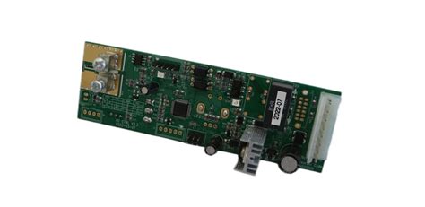
Best Practices For Designing RF PCBs With Rogers Material
Designing RF PCBs with Rogers material requires a meticulous approach to ensure optimal performance and reliability. Rogers Corporation is renowned for its high-frequency laminates, which are specifically engineered to meet the stringent demands of RF and microwave applications. To achieve the best results, it is essential to adhere to certain best practices throughout the design and manufacturing process.
First and foremost, understanding the unique properties of Rogers materials is crucial.
These laminates offer low dielectric constant (Dk) and low loss tangent, which are vital for maintaining signal integrity at high frequencies. Consequently, selecting the appropriate Rogers material based on the specific requirements of your application is the initial step. For instance, Rogers RO4350B is a popular choice for its excellent electrical performance and mechanical stability, making it suitable for a wide range of RF applications.
Once the material is selected, careful attention must be paid to the stack-up design.
The stack-up configuration significantly influences the electrical performance of the PCB. It is advisable to use symmetrical stack-ups to minimize warping and ensure uniform signal propagation. Additionally, maintaining consistent dielectric spacing between layers helps in achieving controlled impedance, which is critical for high-frequency signal transmission.
Transitioning to the layout phase, it is imperative to follow best practices for trace routing.
Minimizing the length of high-frequency signal traces reduces signal loss and potential interference. Employing microstrip or stripline configurations can help in achieving controlled impedance. Furthermore, avoiding sharp bends and right-angle turns in the traces is essential, as these can cause signal reflections and degrade performance. Instead, using gradual curves or mitered bends can mitigate these issues.
Grounding is another critical aspect in RF PCB design.
A solid and continuous ground plane is essential for providing a low-impedance return path for high-frequency signals. This helps in reducing electromagnetic interference (EMI) and crosstalk between adjacent traces. Additionally, stitching vias should be used to connect the ground planes on different layers, ensuring a robust grounding system.
Component placement also plays a pivotal role in the performance of RF PCBs.
Placing sensitive components, such as amplifiers and oscillators, away from noisy elements like power supplies and digital circuits can prevent unwanted interference. Moreover, maintaining adequate spacing between components helps in minimizing parasitic capacitance and inductance, which can adversely affect signal integrity.
Thermal management is another important consideration when designing RF PCBs with Rogers material.
High-frequency circuits can generate significant heat, which, if not properly managed, can lead to performance degradation and reliability issues. Utilizing thermal vias and heat sinks can aid in dissipating heat effectively. Additionally, selecting Rogers materials with good thermal conductivity can further enhance thermal management.
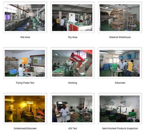
Finally, the manufacturing process must be carefully controlled to preserve the integrity of the Rogers material. Ensuring precise etching and drilling processes is essential to maintain the designed dimensions and tolerances. Moreover, using appropriate soldering techniques and materials can prevent thermal damage to the laminates.
In conclusion, designing RF PCBs with Rogers material involves a comprehensive understanding of the material properties and meticulous attention to detail throughout the design and manufacturing process. By adhering to best practices in material selection, stack-up design, trace routing, grounding, component placement, thermal management, and manufacturing, one can achieve high-performance and reliable RF PCBs that meet the demanding requirements of modern RF and microwave applications.