Rf power amplifier pcb layout
Key Design Considerations for RF Power Amplifier PCB Layout
When designing a printed circuit board (PCB) for an RF power amplifier, several key considerations must be taken into account to ensure optimal performance and reliability. The layout of the PCB plays a crucial role in determining the efficiency, signal integrity, and thermal management of the RF power amplifier. Therefore, understanding and implementing best practices in PCB layout is essential for achieving the desired outcomes.
One of the primary considerations in RF power amplifier PCB layout is the minimization of signal loss and interference.
This can be achieved by carefully planning the placement of components and routing of traces. It is important to keep signal paths as short as possible to reduce the potential for signal degradation. Additionally, the use of controlled impedance traces can help maintain signal integrity by ensuring that the characteristic impedance of the trace matches the impedance of the components and transmission lines.
Another critical aspect is the management of electromagnetic interference (EMI).
EMI can significantly impact the performance of an RF power amplifier, leading to unwanted noise and signal distortion. To mitigate EMI, designers should implement proper grounding techniques, such as using a solid ground plane and ensuring that all ground connections are low impedance. Shielding sensitive components and signal traces can also help reduce the effects of EMI.
Thermal management is another key consideration in RF power amplifier PCB layout.
RF power amplifiers generate significant amounts of heat, which can affect the performance and longevity of the components. Effective thermal management strategies include the use of thermal vias, heat sinks, and thermal pads to dissipate heat away from critical components. Additionally, the placement of components should be optimized to ensure adequate airflow and prevent hotspots.
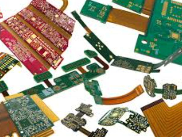
The choice of materials for the PCB is also an important factor in the design of an RF power amplifier.
High-frequency signals require materials with low dielectric loss and stable dielectric constant to minimize signal attenuation and phase distortion. Common materials used in RF PCB design include Rogers, Teflon, and other high-performance laminates. The selection of the appropriate material depends on the specific requirements of the application, such as frequency range, power levels, and environmental conditions.
Component placement and orientation are crucial for minimizing parasitic effects and ensuring proper operation of the RF power amplifier.
Components should be placed in a manner that minimizes the length of high-frequency signal paths and reduces the potential for coupling between adjacent traces. Additionally, the orientation of components should be considered to minimize the impact of parasitic inductance and capacitance.
Power supply decoupling is another important consideration in RF power amplifier PCB layout.
Proper decoupling helps to maintain a stable power supply and reduce noise in the circuit. This can be achieved by placing decoupling capacitors close to the power pins of active components and using multiple capacitors with different values to filter a wide range of frequencies.
In conclusion, the design of an RF power amplifier PCB layout requires careful consideration of various factors to ensure optimal performance and reliability. By minimizing signal loss and interference, managing EMI, implementing effective thermal management strategies, selecting appropriate materials, optimizing component placement and orientation, and ensuring proper power supply decoupling, designers can create a PCB layout that meets the stringent requirements of RF power amplifier applications. These considerations are essential for achieving high efficiency, signal integrity, and long-term reliability in RF power amplifier designs.
Common Mistakes to Avoid in RF Power Amplifier PCB Layout
Designing a printed circuit board (PCB) for an RF power amplifier is a complex task that requires meticulous attention to detail. One of the most common mistakes in RF power amplifier PCB layout is improper grounding. A poor grounding scheme can lead to a myriad of issues, including increased noise, signal distortion, and even complete circuit failure. To avoid this, it is crucial to implement a solid ground plane that minimizes impedance and provides a stable reference point for all components. Additionally, ensuring that the ground plane is continuous and free of gaps can significantly reduce the risk of unwanted interference.
Another frequent error is the incorrect placement of components.
In RF circuits, the physical placement of components can have a substantial impact on performance. Placing components too far apart can lead to increased parasitic inductance and capacitance, which can degrade the signal quality. Conversely, placing components too close together can cause unwanted coupling and crosstalk. Therefore, it is essential to follow the manufacturer’s guidelines for component placement and to use simulation tools to verify the layout before finalizing the design.
Transitioning to the topic of trace routing, improper routing of signal traces is another common pitfall.
RF signals are highly susceptible to losses and reflections, which can be exacerbated by poorly routed traces. To mitigate these issues, it is advisable to use controlled impedance traces and to keep signal paths as short and direct as possible. Additionally, avoiding sharp bends and using gradual curves can help maintain signal integrity. It is also beneficial to route high-frequency signals on the inner layers of the PCB, where they are shielded by the ground planes, thereby reducing the risk of electromagnetic interference (EMI).
Furthermore, neglecting thermal management is a mistake that can have severe consequences.
RF power amplifiers generate significant amounts of heat, which can affect performance and reliability if not properly managed. Incorporating thermal vias, heat sinks, and adequate copper pours can help dissipate heat effectively. Additionally, using materials with high thermal conductivity for the PCB substrate can further enhance thermal management. Ensuring that the layout facilitates efficient heat dissipation is crucial for maintaining the longevity and performance of the RF power amplifier.
In addition to thermal management, power supply decoupling is another critical aspect that is often overlooked.
Inadequate decoupling can lead to power supply noise, which can degrade the performance of the RF power amplifier. To avoid this, it is essential to place decoupling capacitors as close as possible to the power pins of the amplifier. Using multiple capacitors with different values can also help filter out a broader range of noise frequencies. Proper decoupling ensures a stable power supply, which is vital for the optimal operation of the RF power amplifier.
Lastly, failing to consider the impact of parasitic elements can lead to suboptimal performance.
Parasitic inductance and capacitance can arise from various sources, including vias, connectors, and even the PCB material itself. These parasitic elements can affect the impedance of the circuit and introduce unwanted resonances. To minimize their impact, it is essential to use high-quality components and materials, and to carefully design the layout to reduce the number of vias and other discontinuities.
In conclusion, avoiding common mistakes in RF power amplifier PCB layout requires careful planning and attention to detail. By implementing a solid grounding scheme, optimizing component placement, routing signal traces properly, managing thermal issues, ensuring adequate power supply decoupling, and minimizing parasitic elements, designers can significantly enhance the performance and reliability of their RF power amplifiers.
Techniques for Minimizing Signal Loss in RF Power Amplifier PCB Layout
In the design of RF power amplifier PCB layouts, minimizing signal loss is paramount to ensure optimal performance and efficiency. Signal loss can significantly degrade the functionality of RF systems, leading to reduced power output, increased noise, and overall inefficiency. To address these challenges, several techniques can be employed to minimize signal loss in RF power amplifier PCB layouts.
One of the primary techniques involves careful consideration of the PCB material.
The choice of substrate material plays a crucial role in determining the dielectric losses and overall signal integrity. High-frequency laminates, such as Rogers or Teflon-based materials, are often preferred due to their low dielectric constant and minimal loss tangent. These materials help maintain signal integrity by reducing dielectric losses, which are particularly significant at higher frequencies.
Another critical aspect is the layout of transmission lines.
Microstrip and stripline configurations are commonly used in RF PCB designs. Ensuring that these transmission lines are designed with the correct impedance is essential to minimize signal reflections and losses. Impedance matching can be achieved by carefully controlling the width and spacing of the transmission lines, as well as the thickness of the dielectric material. Additionally, the use of ground planes beneath the transmission lines can help maintain consistent impedance and reduce signal loss.
The placement of components is another factor that can influence signal loss.
Components should be strategically placed to minimize the length of signal paths and reduce parasitic inductance and capacitance. Keeping signal paths as short as possible helps to minimize losses due to resistance and inductance. Furthermore, the use of via stitching can help reduce ground loop inductance and improve the overall grounding of the PCB, thereby minimizing signal loss.
Shielding is also an effective technique for minimizing signal loss in RF power amplifier PCB layouts.
Electromagnetic interference (EMI) can significantly degrade signal integrity, leading to increased losses. Implementing shielding techniques, such as using metal enclosures or ground planes, can help mitigate EMI and protect sensitive RF signals. Additionally, the use of decoupling capacitors and ferrite beads can help filter out unwanted noise and further reduce signal loss.
Thermal management is another crucial consideration in RF power amplifier PCB layouts.
Excessive heat can lead to increased resistance and signal loss. Proper thermal management techniques, such as the use of heat sinks, thermal vias, and adequate airflow, can help dissipate heat and maintain optimal operating temperatures. This, in turn, helps to minimize signal loss and ensure the reliable performance of the RF power amplifier.
Moreover, the use of high-quality connectors and soldering techniques can also contribute to minimizing signal loss.
Poor-quality connectors and solder joints can introduce resistance and impedance mismatches, leading to signal degradation. Ensuring that connectors are properly rated for the frequency range and using high-quality soldering techniques can help maintain signal integrity and reduce losses.
In conclusion, minimizing signal loss in RF power amplifier PCB layouts requires a comprehensive approach that considers various factors, including substrate material, transmission line design, component placement, shielding, thermal management, and connector quality. By carefully addressing these aspects, designers can significantly reduce signal loss, thereby enhancing the performance and efficiency of RF power amplifiers. Employing these techniques not only ensures optimal signal integrity but also contributes to the overall reliability and longevity of RF systems.
Best Practices for Thermal Management in RF Power Amplifier PCB Layout
Effective thermal management is a critical aspect of designing RF power amplifier PCB layouts, as it directly impacts the performance, reliability, and longevity of the amplifier. One of the primary considerations in thermal management is the selection of appropriate materials. High thermal conductivity substrates, such as aluminum or copper, are often preferred due to their superior heat dissipation properties. These materials help in efficiently spreading the heat generated by the power amplifier components, thereby reducing the risk of thermal hotspots.
In addition to material selection, the placement of components plays a significant role in thermal management.
Strategically positioning heat-generating components, such as transistors and power resistors, away from temperature-sensitive elements can prevent thermal interference and ensure stable operation. Furthermore, it is advisable to place these components near the edges of the PCB to facilitate better heat dissipation into the surrounding environment. This approach not only minimizes thermal coupling between components but also enhances the overall thermal performance of the PCB.
Another crucial aspect is the use of thermal vias.
These are small, plated holes that connect the top and bottom layers of the PCB, allowing heat to transfer more effectively between layers. By incorporating an adequate number of thermal vias beneath heat-generating components, designers can significantly improve the thermal conductivity of the PCB. This technique is particularly beneficial in multi-layer PCBs, where heat can be efficiently channeled away from critical areas to the outer layers, where it can be dissipated more easily.
Moreover, the implementation of thermal relief pads can further enhance heat dissipation.
These pads are designed to provide a low thermal resistance path between the component and the PCB, thereby facilitating efficient heat transfer. When designing thermal relief pads, it is essential to ensure that they are adequately sized and properly connected to the ground plane. This connection helps in spreading the heat across a larger area, reducing the thermal resistance and improving the overall thermal performance of the PCB.
Additionally, the use of heat sinks and thermal interface materials (TIMs) can significantly aid in managing the thermal load.
Heat sinks, typically made of aluminum or copper, are attached to heat-generating components to increase the surface area available for heat dissipation. TIMs, such as thermal grease or thermal pads, are used to fill the microscopic air gaps between the component and the heat sink, ensuring efficient thermal transfer. By combining heat sinks and TIMs, designers can achieve optimal thermal management, thereby enhancing the reliability and performance of the RF power amplifier.
Furthermore, it is essential to consider the airflow within the enclosure housing the PCB. Adequate ventilation and the use of cooling fans can help in maintaining a stable operating temperature. Proper airflow management ensures that the heat generated by the components is effectively removed from the enclosure, preventing thermal buildup and ensuring consistent performance.
In conclusion, effective thermal management in RF power amplifier PCB layout involves a combination of material selection, strategic component placement, the use of thermal vias and relief pads, and the implementation of heat sinks and TIMs. By adhering to these best practices, designers can ensure that their RF power amplifiers operate reliably and efficiently, even under demanding conditions. This holistic approach to thermal management not only enhances the performance of the amplifier but also extends its operational lifespan, thereby providing a robust and reliable solution for various RF applications.


