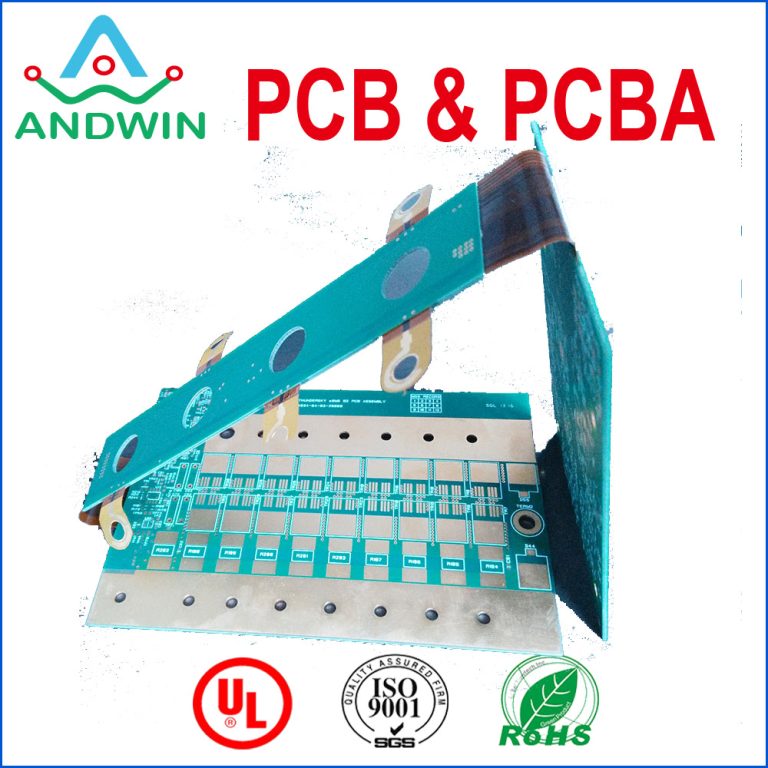
Rigid flex pcb vs rigid pcb
Rigid PCBs are made of solid materials such as fiberglass or epoxy resin and are not flexible.
These boards are used in devices where the components are fixed and do not require any movement.
Rigid PCBs are cheaper to manufacture than Rigid-Flex PCBs and are used in a wide range of applications, from simple electronic devices to complex systems.
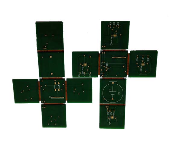
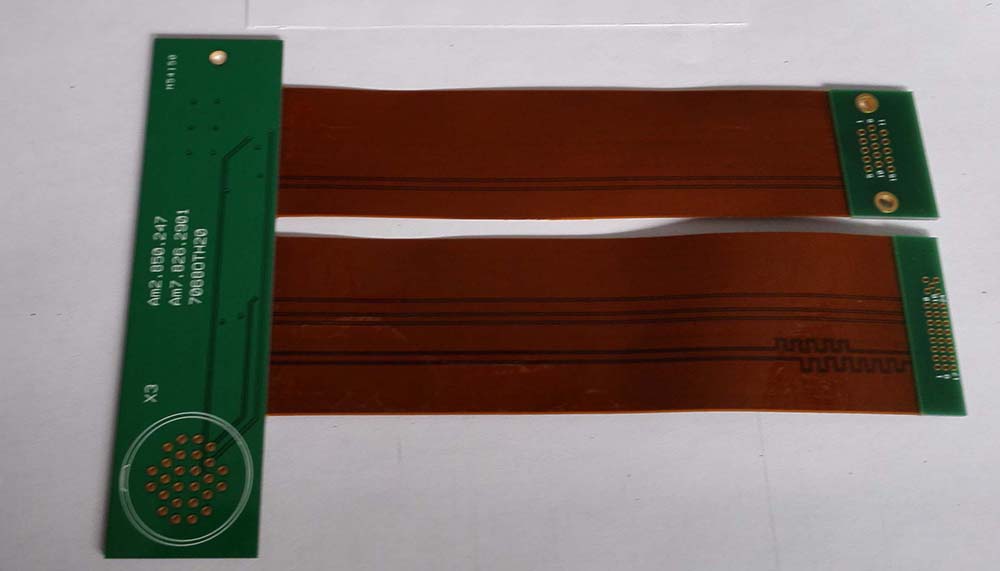
Rigid-Flex PCBs, on the other hand, are a combination of rigid and flexible materials.
These boards are used in devices where the components require movement or flexibility.
Rigid-Flex PCBs are more expensive to manufacture than Rigid PCBs but offer more design flexibility and can be used in devices with complex shapes or where space is limited.
In summary, Rigid PCBs are used in devices where the components are fixed and do not require any movement,
while Rigid-Flex PCBs are used in devices where the components require movement or flexibility.
The difference between rigid flex pcb and rigid pcb
Rigid PCB (Printed Circuit Board) is a type of circuit board that is made of a solid substrate material,
such as fiberglass or plastic, that cannot be bent or flexed.
It is used in applications where the circuit board needs to be fixed in a specific position and not be subject to any movement.
On the other hand, Rigid-Flex PCB is a hybrid type of circuit board that combines both rigid and flexible PCBs.
It is made of a combination of rigid and flexible substrates that are connected by flexible connectors.
This type of PCB can be bent or flexed to fit into a specific shape or design,
which makes it ideal for applications where the circuit board needs to be flexible or fit into a tight space.
In summary, the main difference between rigid PCB and rigid-flex PCB is that the former is rigid and cannot be bent or flexed,
while the latter is a hybrid type of PCB that combines both rigid and flexible substrates and can be bent or flexed to fit into a specific shape or design.

rigid flex pcb design rules
1. Trace width and spacing:
The minimum trace width and spacing should be at least 4 mils.
However, it is recommended to use a trace width of 6 mils or more to ensure better signal integrity.
2. Copper thickness:
The copper thickness should be at least 1 oz.
However, it is recommended to use 2 oz or higher copper thickness for better thermal management.
3. Hole size and spacing:
The minimum hole size should be 0.2 mm. The minimum distance between holes should be at least 0.25 mm.
4. Pad size:
The pad size should be at least 0.4 mm larger than the hole size.
This will ensure that the hole is properly plated and will provide a good connection.
5. Via placement:
Vias should be placed away from the bend area to avoid stress on the vias and the traces.
6. Bend radius: The bend radius should be at least 10 times the thickness of the flex material. This will prevent the material from cracking or breaking.
7. Keep-out zones: Keep-out zones should be defined around the components and connectors to prevent any interference with the flex material.
8. Solder mask: The solder mask should be applied only on the rigid part of the PCB. This will prevent any damage to the flex material during the soldering process.
9. Stiffeners: Stiffeners should be used to support the flex material at the connector and component areas. This will prevent any damage to the flex material due to repeated bending.
10. Testing: Special testing procedures should be used to test the flex material for any defects or damage. This will ensure that the PCB is functioning properly and will prevent any failures.

rigid flex pcb specifications
Rigid-flex PCB specifications can vary depending on the specific application and design requirements, but here are some common specifications:
1. Number of layers:
Rigid-flex PCBs can have multiple layers, typically ranging from 2 to 12 layers.
2. Material:
The rigid portion of the PCB is typically made of FR-4 or other rigid substrate materials,
while the flexible portion is made of polyimide or other flexible materials.
3. Thickness:
The thickness of the rigid and flexible portions can vary depending on the design requirements, but typically range from 0.1mm to 1.6mm.
4. Copper weight:
The copper weight on the rigid and flexible portions can also vary depending on the design requirements,
but typically range from 0.5 oz to 2 oz.
5. Minimum trace width and spacing:
The minimum trace width and spacing on a rigid-flex PCB can be as small as 0.003 inches (0.075mm).
6. Surface finish:
Common surface finishes for rigid-flex PCBs include HASL, ENIG, and OSP.
7. Solder mask color:
The solder mask color can be customized to meet specific design requirements.
8. Testing:
Rigid-flex PCBs undergo various testing procedures to ensure their quality and reliability,
including electrical testing, impedance testing, and thermal testing.
It’s important to note that these specifications can vary depending on the specific application and design requirements, and it’s always best to consult with a PCB manufacturer to determine the best specifications for your project.

how to make rigid flex pcb specifications
1. Determine the design requirements:
Before you start creating the specifications for your rigid-flex PCB, you need to determine the design requirements.
This includes the size and shape of the board, the number of layers,
the type of materials to be used, and any special features or components that need to be included.
2. Choose the materials:
The materials you choose for your rigid-flex PCB will depend on the design requirements.
For example, you may need to choose a specific type of substrate material, copper foil, and adhesive to ensure the board meets your specifications.
3. Define the layers:
The number of layers in your rigid-flex PCB will depend on the complexity of the design.
You need to define the number of layers, the thickness of each layer, and the type of material used for each layer.
4. Define the stack-up:
The stack-up is the arrangement of layers in your rigid-flex PCB.
You need to define the order of the layers, the thickness of each layer, and the type of material used for each layer.
5. Define the routing:
The routing is the path that the electrical signals take through the board.
You need to define the routing for each layer, including the placement of vias, traces, and other components.
6. Define the drilling:
You need to define the drilling requirements for your rigid-flex PCB,
including the size and placement of holes, and the type of drilling equipment to be used.
7. Define the surface finish:
The surface finish is the coating applied to the board to protect it from oxidation and other environmental factors.
You need to define the type of surface finish to be used, such as gold plating or immersion silver.
8. Define the testing requirements:
You need to define the testing requirements for your rigid-flex PCB,
including electrical testing, visual inspection, and other quality control measures.
9. Create a detailed specification document:
Once you have defined all the specifications for your rigid-flex PCB, you need to create a detailed specification document.
This document should include all the information about the design, materials, routing, drilling, surface finish, testing, and any other relevant details.