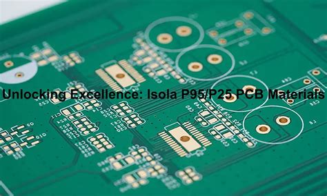
Rogers microwave pcb
Advantages Of Using Rogers Microwave PCB In High-Frequency Applications
Rogers Microwave PCBs, known for their superior performance in high-frequency applications, have become a cornerstone in the realm of advanced electronics. These printed circuit boards, manufactured by Rogers Corporation, are specifically designed to meet the stringent demands of high-frequency and high-speed digital applications. One of the primary advantages of using Rogers Microwave PCBs is their exceptional dielectric properties. Unlike traditional FR-4 materials, Rogers materials exhibit low dielectric constant (Dk) and low dissipation factor (Df), which are crucial for maintaining signal integrity at high frequencies. This ensures minimal signal loss and distortion, making them ideal for applications such as RF and microwave circuits, satellite communications, and radar systems.
In addition to their dielectric properties, Rogers Microwave PCBs offer excellent thermal management capabilities.
High-frequency applications often generate significant amounts of heat, which can adversely affect the performance and reliability of electronic components. Rogers materials are engineered to provide superior thermal conductivity, allowing for efficient heat dissipation and reducing the risk of thermal-related failures. This is particularly important in applications where maintaining consistent performance over a wide temperature range is critical.
Furthermore, Rogers Microwave PCBs are renowned for their dimensional stability.
High-frequency circuits require precise and consistent dimensions to ensure optimal performance. Rogers materials exhibit minimal dimensional changes under varying environmental conditions, such as temperature and humidity fluctuations. This stability is essential for maintaining the integrity of signal paths and ensuring reliable performance over the lifespan of the device. Consequently, designers can achieve tighter tolerances and more accurate impedance control, which are vital for high-frequency applications.
Another significant advantage of Rogers Microwave PCBs is their ease of fabrication.
These materials are compatible with standard PCB manufacturing processes, allowing for seamless integration into existing production lines. This compatibility not only reduces manufacturing costs but also shortens lead times, enabling faster time-to-market for new products. Additionally, Rogers materials are available in a variety of thicknesses and copper cladding options, providing designers with the flexibility to tailor the PCB to their specific requirements.
Moreover, the mechanical robustness of Rogers Microwave PCBs cannot be overlooked.
High-frequency applications often involve harsh operating environments, including exposure to vibration, shock, and mechanical stress. Rogers materials are designed to withstand these conditions, ensuring long-term reliability and durability. This robustness is particularly beneficial in aerospace, defense, and automotive applications, where failure is not an option.
In terms of environmental considerations, Rogers Microwave PCBs are also a sustainable choice.
The materials used in their construction are RoHS compliant, meaning they do not contain hazardous substances that could harm the environment. This compliance is increasingly important as regulatory standards become more stringent and as companies strive to reduce their environmental footprint.
In conclusion, the advantages of using Rogers Microwave PCBs in high-frequency applications are manifold. Their superior dielectric properties, excellent thermal management, dimensional stability, ease of fabrication, mechanical robustness, and environmental compliance make them an ideal choice for a wide range of advanced electronic applications. As technology continues to evolve and the demand for high-frequency performance grows, Rogers Microwave PCBs will undoubtedly play a pivotal role in shaping the future of electronic design and manufacturing.
Design Tips For Optimizing Rogers Microwave PCB Performance
When designing Rogers microwave PCBs, optimizing performance is paramount to ensure the highest levels of efficiency and reliability. One of the first considerations is the selection of the appropriate Rogers material. Rogers Corporation offers a variety of high-frequency laminates, each with unique properties tailored to specific applications. For instance, materials like RO4350B and RO4003C are popular choices due to their low dielectric constant and minimal signal loss, which are crucial for high-frequency applications. Selecting the right material sets the foundation for achieving optimal performance.
Transitioning to the layout design, it is essential to pay close attention to the trace width and spacing.
The impedance of the traces must be controlled to match the characteristic impedance of the transmission lines, typically 50 ohms. This can be achieved by using impedance calculators or simulation software to determine the correct trace dimensions. Additionally, maintaining consistent trace width and spacing throughout the design helps to minimize signal reflections and losses, thereby enhancing overall performance.
Another critical aspect is the management of signal integrity.
High-frequency signals are particularly susceptible to interference and crosstalk. To mitigate these issues, designers should implement proper grounding techniques. A solid ground plane is recommended to provide a low-impedance return path for the signals, which helps to reduce electromagnetic interference (EMI). Furthermore, placing ground vias around high-frequency components and along the edges of the PCB can further enhance signal integrity by providing additional grounding points.
Thermal management is also a key factor in optimizing Rogers microwave PCB performance.
High-frequency circuits often generate significant amounts of heat, which can affect the performance and longevity of the components. To address this, designers should incorporate thermal vias and heat sinks to dissipate heat effectively. Additionally, selecting materials with good thermal conductivity, such as Rogers RT/duroid 6035HTC, can help manage heat more efficiently.
Transitioning to the topic of component placement, it is crucial to position high-frequency components strategically to minimize signal path lengths and reduce potential interference. Placing components too close to each other can lead to unwanted coupling and crosstalk, while placing them too far apart can increase signal path lengths and introduce delays. Therefore, a balanced approach is necessary to ensure optimal performance.
Furthermore, the use of proper decoupling and bypass capacitors is essential in maintaining power integrity.
These capacitors help to filter out noise and provide a stable power supply to the high-frequency components. Placing these capacitors as close as possible to the power pins of the components ensures maximum effectiveness.
Lastly, it is important to consider the manufacturing tolerances and capabilities of the PCB fabrication process.
Rogers materials can be more challenging to work with compared to standard FR4 materials, so it is essential to communicate with the PCB manufacturer to ensure they have experience with Rogers laminates. This includes understanding the specific requirements for drilling, plating, and etching processes to achieve the desired performance characteristics.
In conclusion, optimizing Rogers microwave PCB performance involves a comprehensive approach that includes careful material selection, precise layout design, effective signal and thermal management, strategic component placement, and consideration of manufacturing capabilities. By paying attention to these design tips, engineers can achieve high-performance microwave PCBs that meet the demanding requirements of modern high-frequency applications.
Comparing Rogers Microwave PCB To Other High-Frequency PCB Materials
Rogers microwave PCBs are renowned for their superior performance in high-frequency applications, making them a preferred choice for many engineers and designers. When comparing Rogers microwave PCBs to other high-frequency PCB materials, several key factors come into play, including dielectric constant, loss tangent, thermal management, and cost-effectiveness. Understanding these differences is crucial for making informed decisions in the design and manufacturing of high-frequency electronic devices.
To begin with, the dielectric constant (Dk) is a critical parameter in high-frequency PCB materials.
Rogers materials, such as the popular RO4000 series, offer a stable and low dielectric constant, typically ranging from 2.55 to 3.66. This stability ensures minimal signal distortion and consistent performance across a wide range of frequencies. In contrast, other high-frequency materials, such as FR-4, exhibit higher and less stable dielectric constants, which can lead to signal integrity issues and reduced performance in high-frequency applications.
Another important factor to consider is the loss tangent, which measures the energy loss of a signal as it propagates through the PCB material.
Rogers microwave PCBs are designed with low loss tangents, often below 0.003, which significantly reduces signal attenuation and enhances overall performance. On the other hand, traditional materials like FR-4 have higher loss tangents, typically around 0.02, resulting in greater signal loss and diminished efficiency in high-frequency circuits.
Thermal management is also a crucial aspect when comparing Rogers microwave PCBs to other high-frequency materials.
Rogers materials are engineered to provide excellent thermal conductivity and stability, which is essential for maintaining performance and reliability in demanding environments. For instance, the RO3000 series offers a thermal conductivity of 0.5 W/mK, which helps dissipate heat effectively and prevents thermal-related failures. In contrast, other materials may not offer the same level of thermal performance, potentially leading to overheating and reduced lifespan of the electronic components.
Cost-effectiveness is another consideration when selecting high-frequency PCB materials.
While Rogers microwave PCBs are often more expensive than traditional materials like FR-4, their superior performance and reliability can justify the higher cost in many applications. The long-term benefits of using Rogers materials, such as reduced signal loss, improved thermal management, and consistent dielectric properties, can outweigh the initial investment, especially in critical applications like aerospace, telecommunications, and advanced radar systems.
Moreover, the manufacturing process for Rogers microwave PCBs is designed to accommodate the unique properties of these materials.
Specialized techniques, such as controlled impedance and precise etching, are employed to ensure optimal performance and reliability. This level of precision is often not required for other high-frequency materials, which can result in lower manufacturing costs but may compromise performance and consistency.
In conclusion, when comparing Rogers microwave PCBs to other high-frequency PCB materials, it is evident that Rogers offers distinct advantages in terms of dielectric constant stability, low loss tangent, superior thermal management, and long-term cost-effectiveness. These attributes make Rogers microwave PCBs an ideal choice for high-frequency applications where performance and reliability are paramount. While the initial cost may be higher, the benefits of using Rogers materials can lead to significant improvements in signal integrity, thermal performance, and overall device longevity, making them a worthwhile investment for many advanced electronic applications.
Common Challenges And Solutions In Manufacturing Rogers Microwave PCB
Manufacturing Rogers microwave PCBs presents a unique set of challenges that require specialized solutions to ensure optimal performance and reliability. One of the primary difficulties lies in the material properties of Rogers laminates, which are distinct from traditional FR-4 substrates. Rogers materials, known for their low dielectric constant and low loss tangent, are ideal for high-frequency applications but demand precise handling and processing techniques.
A significant challenge in working with Rogers microwave PCBs is the material’s sensitivity to temperature.
Unlike FR-4, Rogers laminates can exhibit dimensional stability issues when exposed to high temperatures during the soldering process. This can lead to warping or delamination, which compromises the integrity of the PCB. To mitigate this, manufacturers often employ controlled heating and cooling cycles, ensuring that the temperature changes are gradual and within the material’s tolerance limits. Additionally, using low-temperature soldering techniques can help preserve the structural integrity of the Rogers material.
Another common issue is the difficulty in achieving precise etching and drilling.
Rogers materials are softer and more prone to mechanical deformation compared to traditional substrates. This necessitates the use of specialized equipment and techniques to ensure clean and accurate cuts. Laser drilling and controlled-depth routing are often employed to achieve the necessary precision. Furthermore, the use of high-quality, sharp tools can minimize the risk of burring and other defects that could affect the performance of the microwave PCB.
The adhesion of copper to Rogers laminates also poses a challenge.
The bond between the copper and the substrate must be strong enough to withstand the mechanical and thermal stresses encountered during the PCB’s lifecycle. To address this, manufacturers often use a combination of surface treatments and adhesion promoters.
Techniques such as plasma etching or chemical roughening can enhance the surface texture of the Rogers material, improving the mechanical interlock between the copper and the substrate. Additionally, the application of adhesion promoters can further strengthen the bond, ensuring long-term reliability.
Signal integrity is another critical concern in the manufacturing of Rogers microwave PCBs.
The high-frequency signals that these PCBs are designed to handle are highly susceptible to losses and interference. Ensuring minimal signal loss requires meticulous attention to the design and layout of the PCB. This includes maintaining consistent trace widths, minimizing the length of signal paths, and carefully managing the spacing between traces to prevent crosstalk. Advanced simulation tools can aid in optimizing the PCB design to achieve the best possible signal integrity.
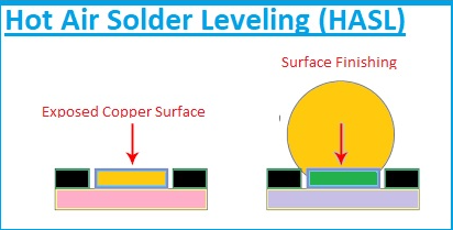
Moreover, the choice of solder mask and surface finish can significantly impact the performance of Rogers microwave PCBs.
The solder mask must be compatible with the Rogers material and should not introduce additional losses or affect the dielectric properties of the substrate. Similarly, the surface finish must provide good solderability while maintaining the integrity of high-frequency signals. Common choices include immersion silver or gold, which offer excellent conductivity and minimal impact on signal performance.
In conclusion, manufacturing Rogers microwave PCBs involves navigating a series of complex challenges that require specialized knowledge and techniques. From managing temperature sensitivity and achieving precise etching to ensuring strong copper adhesion and maintaining signal integrity, each step demands careful consideration and expertise. By employing advanced manufacturing processes and leveraging the unique properties of Rogers materials, manufacturers can produce high-performance microwave PCBs that meet the stringent requirements of modern high-frequency applications..