Signal integrity analysis in high-speed circuit design
Due to the increase in system clock frequency and rise time, signal integrity design has become increasingly important. Unfortunately, most digital circuit designers do not realize the importance of signal integrity issues, or only realize it in the final stage of design.
This article introduces the impact of signal integrity in high-speed digital hardware circuit design on general design.
This includes characteristic impedance control, terminal matching, power and ground planes, signal routing and crosstalk. With this knowledge, a digital circuit designer can notice potential signal integrity issues in the early stages of circuit design, and can also help designers avoid the impact of signal integrity on design performance as much as possible in the design.
Although signal integrity has always been one of the necessary design experiences for hardware engineers, it has long been ignored in digital circuit design. In the era of low-speed logic circuit design, since signal integrity-related issues rarely occurred, considering signal integrity was considered a waste of efficiency. However, in recent years, with the increase in clock rate and rise time, the necessity and design of signal integrity analysis have also increased. Unfortunately, most designers have not noticed it and still rarely consider signal integrity issues in their designs.
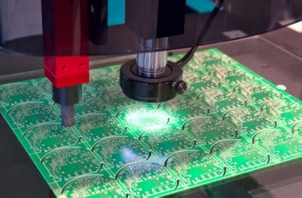
Modern digital circuits can reach frequencies up to GHz and rise times in the 50ps range.
At these rates, an oversight of even a foot in a PCB design trace can cause voltage, delay, and interface problems that are not limited to that trace, but will affect the entire board and adjacent boards.
This problem is particularly severe in mixed circuits.
For example, consider a system with a high-performance ADC to digitize received analog signals. The energy scattered on the digital output port of the ADC device can easily reach 130dB (10,000,000,000,000 times) more than the analog input port. Any noise on the ADC digital port. Signal integrity in design is not a mysterious process. It is critical to be aware of potential problems early in the design process and effectively avoid problems caused by them later. This article discusses some key signal integrity challenges and how to deal with them.
Ensure signal integrity:
1.Isolation
Components on a PCB have a variety of edge rates and various noise differences. The most direct way to improve SI is to achieve it through physical isolation of components on the PCB board based on the device’s edge value and sensitivity. The figure below is an example. In the example, power supply, digital I/O ports and high-speed logic, which are high-risk circuits for clock and data conversion circuits, will be given special consideration. In the first layout, the clock and data converter are placed near the noisy devices. Noise will couple to sensitive circuits and reduce their performance. The second layout has effective circuit isolation, which will be beneficial to the signal integrity of the system design.
2.Impedance, reflection and terminal matching
Impedance control and terminal matching are basic issues in high-speed circuit design. Usually, the RF circuit is considered the most important part in each circuit design, but some digital circuit designs with higher frequencies than RF ignore impedance and terminal matching.
Several fatal effects on digital circuits caused by impedance mismatch are shown in the figure below:
a. Digital signals will cause reflections between the input of the receiving device and the output of the transmitting device. The reflected signal is bounced back and propagates along both ends of the line until it is completely absorbed.
b. Reflected signals cause the signal to ring as it passes through the transmission line. The ringing will affect the voltage and signal delay and completely deteriorate the signal.
c. Mismatched signal paths may cause the signal to radiate to the environment.
The problems caused by impedance mismatch can be minimized by terminal resistors. Terminal resistors are usually placed on the signal line close to the receiving end. The simple approach is to connect a small resistor in series.
The terminal resistor limits the signal rise time and absorbs part of the reflected energy. It is worth noting that impedance matching cannot completely eliminate destructive factors. However, by carefully selecting the right device, the terminal impedance can effectively control the integrity of the signal.
Not all signal lines require impedance control. Some specifications such as Compact PCI require characteristic impedance and terminal impedance characteristics.
For other standards that do not have impedance control specifications and designers do not pay special attention to them. The final standard may change from one application to another. Therefore, it is necessary to consider the length of the signal line (related to the delay Td) and the signal rise time (Tr). The general rule for impedance control is that Td (delay) should be greater than 1/6 of Tr.
3.Inner layer and inner layer segmentation
Factors that digital circuit designers may overlook in current loop design include considerations for the transmission of single-ended signals between two gate circuits (as shown below). The current loop flows from gate A to gate B, and then returns to gate A from the ground plane.
There will be two potential problems in the above figure:
a. The ground plane between points A and B needs to be connected through a low-impedance path. If a larger impedance is connected between the ground planes, voltage backflow will occur between the ground plane pins. This will inevitably cause distortion of the signal amplitude of all devices and superimpose input noise.
b. The area of the current return loop should be as small as possible. The loop is like an antenna. Generally speaking, a larger loop area will increase the chance of loop radiation and conduction. Every circuit designer hopes that the return current can be directly along the signal line, so as to minimize the loop area.
Using large-area grounding can solve the above two problems at the same time. Large-area grounding can provide small impedance between all grounding points, while allowing the return current to return as directly as possible along the signal line.
A common mistake among PCB designers is to drill holes and slots in the ground plane. The figure below shows the current flow when a signal line is on a slotted ground plane. The return current will be forced to bypass the slot, which will inevitably produce a large loop.
Generally speaking, slots cannot be made on the ground power plane. However, in some cases where slots are unavoidable, PCB designers must first determine that there is no signal loop passing through the slotted area. The same rule applies to mixed signal circuits.
Unless multiple ground layers are used in the PCB board. Especially in high-performance ADC circuits, the ground layers that separate analog signals, digital signals and clock circuits can be used to effectively reduce interference between signals. It needs to be emphasized again that in some cases where slots are unavoidable, PCB designers must first determine that there is no signal loop passing through the slotted area.
The area of the interlayer area should also be paid attention to in the power layer with a mirror difference (as shown in the figure below). There is a radiation effect of the power plane layer on the ground plane layer at the edge of the board. Electromagnetic energy leaking from the edge will damage adjacent boards. See Figure a below. Appropriately reduce the area of the power plane layer (see Figure b below) so that the ground plane layer overlaps in a certain area. This will reduce the impact of electromagnetic leakage on adjacent boards

4.Signal wiring
The most important thing to ensure signal integrity is the physical wiring of the signal line. PCB designers are often under work pressure. They must not only complete the design in the shortest possible time, but also ensure the integrity of the signal. Mastering how to balance possible problems with signal spacing will promote the process of system design. High-speed current cannot effectively handle discontinuities in signal lines. The problem of signal discontinuity is most likely to occur in Figure a below. In low-speed circuits, signal discontinuity usually does not need to be considered, but in high-speed circuits, this problem must be considered. Therefore, in circuit design, the method shown in Figure b/c below can effectively ensure signal continuity.
In high-speed circuit design, there is another common problem with signal wiring. If there is no special reason, all short-circuit wiring should be eliminated as much as possible. In high-frequency circuit design, short-circuit wiring is like radiation caused by impedance matching of signal lines.
In the wiring of high-speed circuit design, special attention should be paid to the wiring of differential pairs. The differential pair is driven by two completely complementary signal lines. The differential pair can effectively avoid noise interference and improve the S/N rate. However, the differential pair signal line has particularly high requirements for routing:
- The two lines must be routed as close as possible;
- The two lines must be exactly the same length;
How to reasonably route the differential pair signal line between two devices that are not arranged together is a key issue.
In the above figure a, due to the inconsistent lengths of the two signal lines, there will be some uncertain risks. The correct routing should be in the way shown in the above figure b. The general rule in differential pair routing is: keep the two signal lines at the same distance and close to each other.
5.Crosstalk
In PCB design, crosstalk is another issue worthy of attention. The figure below shows the crosstalk area and the associated electromagnetic area between three adjacent pairs of parallel signal lines in a PCB. When the interval between signal lines is too small, the electromagnetic areas between signal lines will affect each other, resulting in signal deterioration, which is crosstalk.
Crosstalk can be solved by increasing the spacing between signal lines. However, PCB designers are often constrained by increasingly tight routing space and narrow signal line spacing; since there are no more options in the design, some crosstalk problems are inevitably introduced into the design. Obviously, PCB designers need to have a certain ability to manage crosstalk problems. Many reliable spacing rules have been developed over the years. A rule that is generally recognized by the industry is the 3W rule, that is, the spacing between adjacent signal lines should be at least 3 times the width of the signal line. However, the acceptable signal line spacing in practice depends on factors such as the actual application, working environment, and design redundancy. The signal line spacing changes from one situation to another and each calculation. Therefore, when crosstalk problems are inevitable, crosstalk should be quantified. This can be represented by computer simulation technology. Using the simulator, designers can determine the signal integrity effect and estimate the crosstalk impact of the system.
6.Power supply decoupling
Power supply decoupling is a standard practice in digital circuit design now, and it will help reduce noise problems on the power supply line. A clean power supply is essential to designing a high-performance circuit. High-frequency noise superimposed on the power supply will cause problems for each adjacent digital device. Typical noise sources are ground bounce, signal radiation, or digital devices themselves. The simplest way to solve power supply noise is to use capacitors to decouple high-frequency noise from the ground. An ideal decoupling capacitor provides a low-resistance path to the ground for high-frequency noise, thereby eliminating power supply noise. Decoupling capacitors are selected based on actual applications. Most designers will choose surface-mount capacitors as close to the power pins as possible, and the capacitance should be large enough to provide a low-resistance path to the ground for foreseeable power supply noise. The common problem with using decoupling capacitors is that decoupling capacitors cannot be simply regarded as capacitors. There are several situations:
a. The packaging of the capacitor will cause parasitic inductance;
b. The capacitor will bring some equivalent resistance;
c. The wire between the power pin and the decoupling capacitor will bring some equivalent inductance;
d. The wire between the ground pin and the ground plane will bring some equivalent inductance; The effects caused by this:
a. The capacitor will cause a resonance effect at a specific frequency and the network impedance generated by it will have a greater impact on the signals in the adjacent frequency band;
b. The equivalent resistance (ESR) will also affect the low-resistance path formed for high-speed noise decoupling;
The following summarizes the effects caused by this on a digital designer:
a. The leads from the Vcc and GND pins on the device need to be treated as small inductors. Therefore, it is recommended to make the Vcc and GND leads as short and thick as possible in the design.
b. Select capacitors with low ESR effects, which will help improve the decoupling of the power supply;
c. Selecting small package capacitor devices will reduce the package inductance. Replacing devices with smaller packages will cause changes in temperature characteristics. Therefore, after selecting a small package capacitor, the layout of the device in the design needs to be adjusted.
In the design, replacing the X7R type capacitor with a Y5V type capacitor can ensure a smaller package and lower equivalent inductance, but it will also cost more device costs to ensure high temperature characteristics.
In the design, the decoupling of low-frequency noise with large-capacity capacitors should also be considered. Using separate electrolytic capacitors and tantalum capacitors can greatly improve the cost-effectiveness of the device.
7.Summary:
Signal integrity is one of the most important issues throughout high-speed digital circuit design; here are some suggestions for ensuring signal integrity in digital circuit design:
a. Physically isolate sensitive components from noisy components;
b. Impedance control, reflection and signal terminal matching;
c. Use continuous power and ground plane layers;
d. Try to avoid right angles in wiring;
e. The length of differential pair wiring is equal;
f. Crosstalk should be considered in high-speed circuit design;
g. Power supply decoupling problem;
A good grasp of the above-mentioned problems in digital circuit design can help digital circuit designers find as many potential problems in circuit design as possible in the early stage of circuit design.


