Solder metal core pcb
Advantages Of Using Solder Metal Core PCBs In High-Power Applications
Solder metal core printed circuit boards (PCBs) have emerged as a pivotal technology in high-power applications, offering a range of advantages that make them indispensable in various industries.
These PCBs are designed with a metal core, typically aluminum or copper, which serves as a heat sink to dissipate heat more efficiently than traditional fiberglass-based PCBs. This unique construction provides several benefits that are particularly valuable in high-power applications, where thermal management and reliability are paramount.
One of the primary advantages of using solder metal core PCBs in high-power applications is their superior thermal conductivity.
The metal core acts as a conduit for heat, allowing it to be transferred away from critical components more effectively. This is crucial in high-power applications, where excessive heat can lead to component failure, reduced performance, and shortened lifespan. By efficiently managing heat, solder metal core PCBs help maintain optimal operating temperatures, thereby enhancing the reliability and longevity of electronic devices.
In addition to improved thermal management, solder metal core PCBs offer enhanced mechanical stability.
The metal core provides a robust foundation that can withstand the mechanical stresses associated with high-power applications. This is particularly important in environments where electronic devices are subjected to vibrations, shocks, and other physical forces. The increased mechanical stability ensures that the PCB maintains its structural integrity, reducing the risk of damage and ensuring consistent performance over time.
Furthermore, solder metal core PCBs are known for their excellent electrical performance.
The metal core not only aids in heat dissipation but also serves as a ground plane, which can improve signal integrity and reduce electromagnetic interference (EMI). This is especially beneficial in high-power applications where maintaining signal quality is critical. The reduced EMI helps in achieving cleaner signals, which is essential for the proper functioning of sensitive electronic components.
Another significant advantage of solder metal core PCBs is their ability to support higher current densities.
The metal core can handle larger amounts of current without overheating, making these PCBs ideal for applications that require substantial power delivery. This capability is particularly valuable in industries such as automotive, aerospace, and industrial automation, where high-power devices are commonplace. The ability to manage higher current densities without compromising performance or safety is a key factor that sets solder metal core PCBs apart from traditional PCB technologies.
Moreover, the use of solder metal core PCBs can lead to cost savings in the long run.
While the initial cost of these PCBs may be higher than that of traditional fiberglass-based PCBs, their enhanced thermal management and reliability can result in lower maintenance costs and fewer replacements. This makes them a cost-effective solution for high-power applications, where the cost of downtime and repairs can be significant.
In conclusion, solder metal core PCBs offer a multitude of advantages that make them highly suitable for high-power applications. Their superior thermal conductivity, enhanced mechanical stability, excellent electrical performance, ability to support higher current densities, and potential for cost savings collectively contribute to their growing popularity in various industries. As the demand for high-power electronic devices continues to rise, the adoption of solder metal core PCBs is likely to increase, driven by their ability to meet the stringent requirements of these demanding applications.
Step-By-Step Guide To Manufacturing Solder Metal Core PCBs
Manufacturing solder metal core printed circuit boards (PCBs) is a meticulous process that requires precision and attention to detail. The journey begins with the selection of appropriate materials, which is crucial for ensuring the durability and functionality of the final product. Metal core PCBs typically use aluminum or copper as the core material due to their excellent thermal conductivity properties. This core is essential for dissipating heat away from critical components, thereby enhancing the overall performance and longevity of the PCB.
Once the core material is selected, the next step involves designing the PCB layout.
This phase requires the use of specialized software to create a detailed blueprint of the circuit. The design must account for the placement of components, the routing of electrical connections, and the thermal management requirements. It is imperative to ensure that the design adheres to industry standards and specifications to avoid any issues during the manufacturing process.
Following the design phase, the manufacturing process moves on to the preparation of the metal core.
The core material is cut to the required dimensions and cleaned thoroughly to remove any contaminants that could affect the adhesion of subsequent layers. This step is critical as any impurities on the core surface can lead to defects in the final product.
The next stage involves the application of an insulating layer over the metal core.
This layer is typically made of a dielectric material that provides electrical insulation while maintaining good thermal conductivity. The insulating layer is applied using a lamination process, which involves pressing the dielectric material onto the metal core under high temperature and pressure. This ensures a strong bond between the core and the insulating layer, which is essential for the structural integrity of the PCB.
Once the insulating layer is in place, the process continues with the application of the copper foil.
The copper foil is laminated onto the insulating layer using a similar process, ensuring a uniform and secure bond. This copper layer will form the conductive pathways for the electrical signals on the PCB. After lamination, the copper layer undergoes a series of chemical treatments to create the desired circuit pattern. This involves coating the copper with a photoresist material, exposing it to ultraviolet light through a photomask, and then etching away the unwanted copper to reveal the circuit design.
With the circuit pattern established, the next step is to drill holes for the through-hole components and vias.
These holes are drilled using precision machinery to ensure accurate placement and size. After drilling, the holes are plated with copper to create electrical connections between the different layers of the PCB.
The final stages of manufacturing involve the application of a solder mask and surface finish. The solder mask is a protective layer that covers the copper traces, preventing oxidation and short circuits. It also helps to define the areas where solder will be applied during the assembly process. The surface finish, such as HASL (Hot Air Solder Leveling) or ENIG (Electroless Nickel Immersion Gold), is applied to the exposed copper areas to enhance solderability and protect against corrosion.
In conclusion, manufacturing solder metal core PCBs is a complex process that requires careful planning and execution. Each step, from material selection to surface finishing, plays a vital role in ensuring the quality and reliability of the final product. By adhering to industry standards and employing precise manufacturing techniques, it is possible to produce high-performance PCBs that meet the demanding requirements of modern electronic applications.
Thermal Management Solutions With Solder Metal Core PCBs
Solder metal core printed circuit boards (PCBs) have emerged as a pivotal solution in the realm of thermal management for electronic devices. As electronic components become increasingly powerful and compact, the need for efficient heat dissipation mechanisms has never been more critical. Solder metal core PCBs address this necessity by integrating a metal core, typically aluminum or copper, which significantly enhances thermal conductivity compared to traditional fiberglass-based PCBs.
The primary advantage of solder metal core PCBs lies in their ability to effectively manage and dissipate heat generated by high-power components.
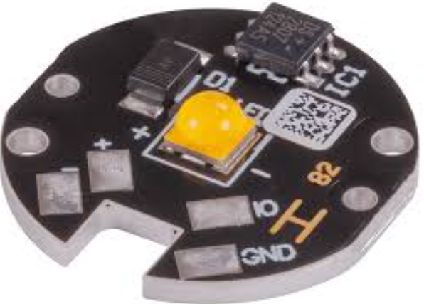
This is particularly crucial in applications such as LED lighting, power supplies, and automotive electronics, where excessive heat can lead to performance degradation or even failure. By incorporating a metal core, these PCBs provide a direct thermal path from the heat-generating components to the heat sink, thereby reducing thermal resistance and ensuring more efficient heat transfer.
Moreover, the use of solder metal core PCBs contributes to the overall reliability and longevity of electronic devices.
Excessive heat can cause thermal stress, leading to the expansion and contraction of materials, which in turn can result in mechanical failures such as solder joint fatigue or delamination. By maintaining lower operating temperatures, solder metal core PCBs mitigate these risks, thereby enhancing the durability and operational lifespan of the devices they are used in.
In addition to their thermal management capabilities, solder metal core PCBs offer several other benefits.
For instance, they exhibit superior mechanical strength and rigidity compared to their non-metal core counterparts. This makes them particularly suitable for applications that are subject to mechanical stress or vibration, such as automotive and industrial electronics. Furthermore, the metal core provides a stable platform for mounting components, which can improve the overall assembly process and reduce the likelihood of defects.
The manufacturing process of solder metal core PCBs involves several critical steps to ensure optimal performance.
Initially, a metal core is selected based on the specific thermal and mechanical requirements of the application. This core is then laminated with dielectric materials and copper layers, which are subsequently etched to form the desired circuit patterns. The final step involves the application of solder mask and surface finishes, which protect the circuitry and facilitate component assembly.
Despite their numerous advantages, solder metal core PCBs also present certain challenges.
One of the primary considerations is the cost, as the inclusion of a metal core and the associated manufacturing processes can be more expensive than traditional PCB fabrication. However, this cost is often justified by the enhanced performance and reliability that these PCBs provide. Additionally, the design and layout of solder metal core PCBs require careful consideration to ensure effective thermal management and to avoid potential issues such as thermal expansion mismatches.
In conclusion, solder metal core PCBs represent a significant advancement in thermal management solutions for electronic devices. By leveraging the superior thermal conductivity of metal cores, these PCBs effectively dissipate heat, thereby enhancing the performance, reliability, and longevity of high-power electronic applications. While they may present certain cost and design challenges, the benefits they offer make them an invaluable component in the ever-evolving landscape of electronic technology. As the demand for more powerful and compact electronic devices continues to grow, the role of solder metal core PCBs in ensuring efficient thermal management will undoubtedly become increasingly important.
Comparing Solder Metal Core PCBs To Traditional FR4 PCBs
When comparing solder metal core PCBs to traditional FR4 PCBs, it is essential to understand the fundamental differences between these two types of printed circuit boards. Both have their unique advantages and applications, but the choice between them often depends on the specific requirements of the electronic device in question.
Solder metal core PCBs, also known as metal core printed circuit boards (MCPCBs), are designed with a metal substrate, typically aluminum or copper, which serves as the core material. This metal core provides superior thermal conductivity, which is a critical factor in high-power applications where heat dissipation is paramount. In contrast, traditional FR4 PCBs are constructed using a fiberglass-reinforced epoxy laminate, which, while offering good electrical insulation and mechanical strength, does not match the thermal performance of metal core alternatives.
One of the primary advantages of solder metal core PCBs is their ability to efficiently manage heat.
The metal core acts as a heat sink, drawing heat away from critical components and dissipating it more effectively than the FR4 substrate. This characteristic makes MCPCBs particularly suitable for applications such as LED lighting, power supplies, and automotive electronics, where thermal management is crucial to maintaining performance and longevity. On the other hand, FR4 PCBs, with their lower thermal conductivity, may require additional cooling mechanisms, such as heat sinks or fans, to achieve similar thermal performance.
Moreover, the mechanical properties of solder metal core PCBs offer additional benefits.
The metal substrate provides enhanced rigidity and durability, making these PCBs less prone to warping or mechanical damage under stress. This robustness is particularly advantageous in environments subject to vibration or mechanical shock, such as industrial machinery or automotive systems. Conversely, while FR4 PCBs are generally reliable and versatile, they may not offer the same level of mechanical resilience as their metal core counterparts.
However, it is important to consider the potential drawbacks of solder metal core PCBs. One significant factor is cost.
The materials and manufacturing processes involved in producing MCPCBs are typically more expensive than those for FR4 PCBs. This cost difference can be a deciding factor for applications where budget constraints are a primary concern. Additionally, the weight of metal core PCBs can be higher than that of FR4 PCBs, which may be a consideration in weight-sensitive applications such as aerospace or portable electronics.
Furthermore, the design and fabrication processes for solder metal core PCBs can be more complex.
The presence of a metal core requires specialized techniques for drilling, routing, and plating, which can increase production time and complexity. Designers must also account for the thermal expansion properties of the metal core, which differ from those of the FR4 material, to ensure reliable performance over a range of operating temperatures.
In conclusion, the choice between solder metal core PCBs and traditional FR4 PCBs hinges on a careful evaluation of the specific requirements of the application. While MCPCBs offer superior thermal management and mechanical robustness, they come with higher costs and potential design complexities. FR4 PCBs, on the other hand, provide a cost-effective and versatile solution for a wide range of electronic devices but may require additional measures to address thermal and mechanical challenges. By weighing these factors, engineers and designers can make informed decisions to optimize the performance and reliability of their electronic systems.


