The Impact of PCB Materials on Thermal Management in Electronic Devices
Introduction
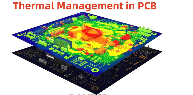
Thermal management is a critical aspect of modern electronic design, particularly as devices become more compact and power-dense. Printed Circuit Boards (PCBs) serve as the backbone of electronic systems, providing mechanical support and electrical connectivity. However, the choice of PCB material significantly influences heat dissipation, which in turn affects device reliability, performance, and longevity.
This article explores how different PCB materials impact thermal management, discussing key properties such as thermal conductivity, coefficient of thermal expansion (CTE), glass transition temperature (Tg), and dielectric properties. We will also examine common PCB substrate materials, their thermal characteristics, and strategies for optimizing thermal performance in electronic designs.
1. Key Thermal Properties of PCB Materials
1.1 Thermal Conductivity
Thermal conductivity (measured in W/m·K) determines how efficiently a material conducts heat. High thermal conductivity helps distribute heat evenly, preventing localized hot spots.
- Standard FR-4: ~0.3 W/m·K (poor conductor)
- Metal-core PCBs (e.g., aluminum): 1-3 W/m·K
- Ceramic substrates (AlN, BeO): 150-300 W/m·K
1.2 Coefficient of Thermal Expansion (CTE)
CTE describes how much a material expands when heated. A mismatch between PCB and component CTEs can cause mechanical stress, leading to solder joint failures.
- FR-4: High CTE (~14-17 ppm/°C)
- Polyimide: Lower CTE (~12 ppm/°C)
- Ceramics: Very low CTE (~4-6 ppm/°C)
1.3 Glass Transition Temperature (Tg)
Tg is the temperature at which a PCB substrate transitions from rigid to flexible. Operating above Tg degrades mechanical and electrical properties.
- Standard FR-4: ~130-140°C
- High-Tg FR-4: >170°C
- Polyimide: >250°C
1.4 Dielectric Properties
While primarily affecting electrical performance, dielectric properties also influence thermal behavior. Materials with low dielectric loss (e.g., PTFE) reduce heat generation from high-frequency signals.
2. Common PCB Materials and Their Thermal Performance
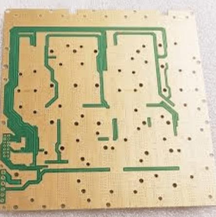
2.1 FR-4 (Flame Retardant 4)
- Pros: Low cost, widely available, good electrical insulation.
- Cons: Poor thermal conductivity, moderate Tg, high CTE.
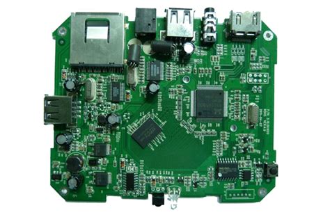
- Applications: Consumer electronics, low-power devices.
2.2 Metal-Core PCBs (MCPCBs)
- Pros: Excellent heat dissipation (aluminum/copper cores), low thermal resistance.
- Cons: Higher cost, limited multilayer options.
- Applications: LED lighting, power electronics.
2.3 Polyimide
- Pros: High Tg, flexible, good thermal stability.
- Cons: Expensive, lower thermal conductivity than ceramics.
- Applications: Aerospace, military, flexible circuits.
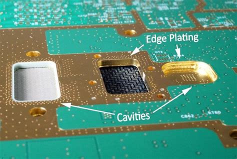
2.4 Ceramic Substrates (Alumina, Aluminum Nitride)
- Pros: Extremely high thermal conductivity, low CTE.
- Cons: Brittle, expensive, difficult to manufacture.
- Applications: High-power RF, automotive, industrial systems.
2.5 PTFE (Teflon)
- Pros: Low dielectric loss, stable at high frequencies.
- Cons: Poor thermal conductivity, soft.
- Applications: RF/microwave circuits.
3. Advanced Materials for Enhanced Thermal Management
3.1 Thermally Conductive Fillers
Adding ceramic particles (e.g., boron nitride, alumina) to PCB substrates improves thermal conductivity without significantly increasing cost.
3.2 Graphene-Enhanced PCBs
Graphene offers ultra-high thermal conductivity (~5000 W/m·K). Research is ongoing to integrate it into PCB laminates.
3.3 Liquid Crystal Polymer (LCP)
LCPs provide low moisture absorption and stable CTE, useful for high-frequency applications.

4. Design Strategies for Improved Thermal Management
- Thermal Vias: Plated holes that transfer heat to inner layers or heatsinks.
- Copper Thickness: Thicker copper layers enhance heat spreading.
- Heatsinks & Thermal Pads: Used in conjunction with high-conductivity substrates.
- Layer Stackup Optimization: Placing high-power components near thermally conductive layers.
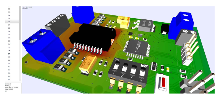
5. Case Study: PCB Material Selection in Power Electronics
A comparison between FR-4 and aluminum-core PCBs in a 100W power converter shows:
- FR-4: Junction temperature reaches 120°C, risking failure.
- Aluminum PCB: Junction temperature stabilizes at 85°C, improving reliability.
6. Future Trends in PCB Thermal Management
- Embedded Cooling: Microfluidic channels within PCBs for active cooling.
- Hybrid Materials: Combining polymers with high-conductivity metals/ceramics.
- AI-Driven Thermal Optimization: Machine learning for predictive thermal modeling.
Conclusion
The selection of PCB materials plays a pivotal role in thermal management, directly impacting device performance and lifespan. While FR-4 remains popular for cost-sensitive applications, advanced materials like metal-core PCBs and ceramics are essential for high-power designs. Future innovations in thermally conductive composites and cooling technologies will further push the boundaries of PCB thermal performance.
Designers must carefully balance thermal, electrical, and mechanical requirements when selecting PCB materials to ensure optimal reliability in modern electronics.