The Role of Jumpers in Printed Circuit Boards (PCBs)
Introduction
In the intricate world of printed circuit board (PCB) design and manufacturing, jumpers (commonly called “jumpers” or “jumpers”) serve as essential components that provide flexibility, functionality, and problem-solving capabilities. These small but mighty conductive connections play multiple roles in electronic circuits, from enabling configuration options to facilitating repairs. This 2000-word article explores the various functions, types, and applications of jumpers in PCBs, providing a comprehensive understanding of their importance in modern electronics.
Understanding PCB Jumpers
A jumper in PCB terminology refers to an electrical connection that links two or more points in a circuit without using the standard copper traces of the board. These connections can be temporary or permanent, depending on their intended purpose. Jumpers typically consist of:
- Short lengths of insulated wire
- Zero-ohm resistors (acting as bridged connections)
- Dedicated jumper pins with removable caps
- Surface-mount jumper pads
The simplest form is a wire jumper manually installed to create a connection where none existed in the original PCB layout. More sophisticated versions include programmable jumpers and surface-mount options that can be changed during manufacturing.
Primary Functions of PCB Jumpers
1. Circuit Configuration and Customization
Jumpers serve as hardware configuration tools that allow the same PCB to support different functionalities or specifications. By changing jumper positions, engineers can:
- Enable or disable specific features
- Select between different operating modes
- Adjust voltage levels
- Choose between clock speeds
- Configure communication protocols (I2C, SPI, etc.)
This flexibility proves invaluable for manufacturers producing multiple product variants from a single PCB design, significantly reducing production costs and complexity.
2. Debugging and Testing
During PCB development and production testing, jumpers provide critical access points for:
- Isolating circuit sections for individual testing
- Injecting test signals
- Measuring specific node voltages
- Bypassing malfunctioning components
- Connecting debugging equipment
Test engineers often use jumper wires to temporarily modify circuits during troubleshooting without requiring permanent changes to the board.
3. Repair and Rework Facilitation
When PCBs develop faults or require modifications, jumpers offer practical solutions:
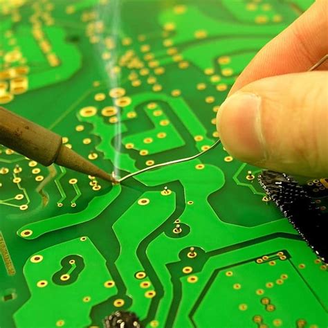
- Bypassing broken traces: If a copper trace becomes damaged (due to physical stress, corrosion, or manufacturing defects), a jumper wire can restore the connection.
- Implementing engineering changes: Rather than respinning the entire PCB for minor design revisions, jumpers can implement the modifications.
- Correcting design errors: Discovered post-production, some design flaws can be rectified with strategic jumper placements.
4. Overcoming Design Limitations
Even with advanced PCB design software, certain physical constraints sometimes necessitate jumpers:
- Crossing traces: In single-layer PCBs where traces cannot cross without connecting, jumpers allow one trace to “hop over” another.
- Routing challenges: Complex designs may require jumpers when routing becomes impossible within space constraints.
- High-current paths: Sometimes, standard trace widths cannot handle required current, so thicker jumper wires supplement the connection.
5. Firmware and Hardware Interaction
Many systems use jumper positions to communicate configuration information to firmware or software:
- Boot mode selection (normal operation vs. programming mode)
- Hardware revision identification
- Expansion board detection
- Security mode activation
Types of PCB Jumpers
1. Wire Jumpers
The most basic type consists of insulated wires manually soldered between points. These are common in:
- Prototype boards
- Hand-assembled electronics
- Repair scenarios
2. Header Jumpers
These use plastic-covered pins with removable conductive caps (shunts). Commonly seen in:
- Computer motherboards (clearing CMOS, selecting voltages)
- Development boards (configuration options)
- Industrial control boards
3. Surface-Mount Jumpers
Designed for automated assembly, these include:
- Zero-ohm resistors (functionally identical to wire jumpers)
- Selectable solder bridges (pads that can be connected with solder)
- Tiny switches or buttons
4. Programmable Jumpers
Advanced systems may use:
- Electronically-controlled switches (FETs, MEMS)
- FPGAs with configurable I/O
- Digital potentiometers acting as soft jumpers
Jumper Implementation Considerations
When incorporating jumpers into PCB designs, engineers must account for several factors:
Electrical Characteristics
- Current carrying capacity (wire gauge or trace width)
- Voltage isolation requirements
- Signal integrity (especially for high-frequency signals)
- Contact resistance (for removable jumpers)
Physical Design
- Clear labeling (J1, J2, etc.) and silkscreen indications
- Adequate spacing for tools to access removable jumpers
- Strain relief for wire jumpers
- Orientation consistency across the board
Reliability Factors
- Corrosion resistance (gold plating on contacts)
- Mechanical stability (secure mounting)
- Environmental protection (conformal coating considerations)
- Vibration resistance
Manufacturing and Assembly
- Automated insertion compatibility
- Soldering requirements
- Testing accessibility
- Rework feasibility
Advanced Jumper Applications
1. Field-Programmable Gate Arrays (FPGAs)
Modern FPGAs often use jumper-like configuration options to set up:
- I/O bank voltages
- Boot sources
- Clock configurations
2. Internet of Things (IoT) Devices
Compact IoT devices frequently employ jumpers for:
- Selecting communication interfaces
- Enabling low-power modes
- Configuring sensor options
3. Automotive Electronics
Vehicle electronics use ruggedized jumpers for:
- Enabling diagnostic modes
- Selecting regional variations
- Configuring optional equipment
4. Aerospace and Defense Systems
High-reliability applications implement jumpers with:
- Hermetic sealing
- Vibration-proof designs
- Tamper-evident features
Best Practices for Jumper Usage
To maximize the benefits while minimizing potential issues, follow these guidelines:
- Document Thoroughly: Clearly indicate jumper functions in schematics, assembly drawings, and user manuals.
- Standardize: Use consistent jumper types and labeling across product lines.
- Consider Alternatives: Evaluate whether software configuration could replace hardware jumpers when feasible.
- Plan for Expansion: Leave unused jumper positions for future enhancements or fixes.
- Test Jumper Settings: Verify all possible configurations during quality assurance testing.
- Protect Critical Jumpers: Implement safeguards against accidental changes in mission-critical applications.
Common Jumper-Related Issues and Solutions
Despite their utility, jumpers can introduce challenges:
Problem: Accidental Configuration Changes
- Solution: Use tamper-evident seals or software confirmation for critical settings.
Problem: Corrosion or Dirty Contacts
- Solution: Specify gold-plated contacts for removable jumpers in harsh environments.
Problem: Vibration-Induced Disconnection
- Solution: Use locking jumper shunts or conformal coating in high-vibration applications.
Problem: Confusing Jumper Settings
- Solution: Implement clear silkscreen labels and comprehensive documentation.
The Future of PCB Jumpers
As electronics continue evolving, jumper technology adapts:
- Virtual Jumpers: Software-configurable options increasingly replace physical jumpers where possible.
- Smaller Form Factors: Miniaturization drives development of microscopic jumper solutions for high-density boards.
- Self-Healing Jumpers: Emerging materials may enable jumpers that automatically repair broken connections.
- Smart Jumpers: Incorporating sensing capabilities to report their status to system controllers.
Conclusion
PCB jumpers, though often small and inconspicuous, play vital roles in electronics manufacturing, testing, configuration, and repair. Their versatility makes them indispensable tools for engineers navigating the complex landscape of circuit board design and production. From simple wire bridges to sophisticated programmable interfaces, jumpers provide the flexibility needed to adapt to changing requirements, overcome design limitations, and extend product lifecycles.
Understanding jumper functions and proper implementation techniques enables designers to create more adaptable, maintainable, and cost-effective electronic systems. As technology progresses, the fundamental concept of the jumper continues to find new expressions while maintaining its core purpose: providing reconfigurable connections in an otherwise fixed circuit landscape.
Whether you’re a PCB designer considering jumper placement, a technician troubleshooting a circuit, or an end-user configuring hardware options, appreciating the humble jumper’s significance leads to better electronic design practices and more effective problem-solving approaches. In the constantly evolving world of electronics, the jumper remains a timeless solution to the persistent challenge of maintaining flexibility within fixed physical constraints.