The Ultimate Guide to USB-C Breakout Boards: Design, Applications, and Best Practices
Introduction to USB-C Breakout Boards
In the ever-evolving world of electronics and connectivity, USB-C breakout boards have emerged as essential tools for engineers, hobbyists, and product developers. These compact boards serve as intermediaries between the complex USB Type-C connector and more accessible connection points, making it easier to work with this advanced interface standard.
USB-C, officially known as USB Type-C, represents a significant leap forward in connectivity technology. Unlike its predecessors, this reversible 24-pin connector supports faster data transfer rates (up to 40 Gbps with USB4), higher power delivery (up to 240W with USB PD 3.1), and alternate modes that allow for video output and other specialized functions. However, the very features that make USB-C so powerful also make it challenging to work with directly—this is where breakout boards prove invaluable.
Understanding USB-C Breakout Board Architecture
Core Components
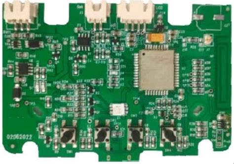
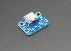
A typical USB-C breakout board consists of several key components:
- USB Type-C Receptacle: The physical connector that accepts USB-C plugs, usually surface-mounted on the board.
- Breakout Pins/Headers: These provide access to the various signals in the USB-C interface, often arranged in a 2.54mm pitch for easy prototyping.
- Supporting Circuitry: May include resistors for configuration (like the 5.1kΩ pull-down resistors for CC lines), ESD protection diodes, and sometimes level shifters.
- Power Regulation: Some advanced breakout boards include voltage regulators to handle USB Power Delivery.
Pin Configuration and Functions
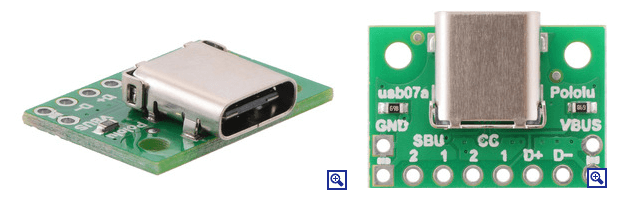
The USB-C connector has 24 pins arranged symmetrically to enable the reversible plug orientation. A quality breakout board will provide access to all these pins, typically labeled according to the USB-C specification:
- Power Pins: VBUS (power), GND (ground)
- Configuration Channel: CC1, CC2 (used for cable orientation detection and power negotiation)
- Data Pins: D+/D- (USB 2.0), SSTX/SSRX (SuperSpeed differential pairs)
- Sideband Use: SBU1, SBU2 (used for alternate modes)
- VCONN: Power for active cables
Types of USB-C Breakout Boards
Basic Passive Breakout Boards
These are the simplest form, providing direct access to all USB-C pins without any active components. They’re ideal for situations where you need to interface with the raw signals and handle all protocol aspects in your main circuit.
Active Breakout Boards with USB PD Controller
More advanced versions incorporate a USB Power Delivery controller chip (such as the STUSB4500 or FUSB302) that handles power negotiation automatically. These are essential when working with higher power applications (beyond 15W).
Specialized Breakout Boards
Some breakout boards are designed for specific purposes:
- Audio Adapter Breakout Boards: Focus on the audio accessory mode features
- DisplayPort Alt Mode Breakouts: Provide easy access to DisplayPort signals
- Debug Accessory Mode Breakouts: For development and testing purposes
Key Applications of USB-C Breakout Boards
Prototyping and Development
USB-C breakout boards are indispensable in the prototyping phase of any project involving USB-C connectivity. They allow engineers to:
- Test USB-C functionality without designing a custom PCB
- Experiment with different power delivery configurations
- Develop and debug USB communication protocols
Custom Device Integration
Many modern devices are moving to USB-C as their sole connectivity port. Breakout boards enable:
- Creating custom interfaces for these devices
- Developing specialized charging solutions
- Building docking stations or port replicators
Educational Purposes
For students and electronics enthusiasts, USB-C breakout boards serve as excellent learning tools to:
- Understand the USB-C specification hands-on
- Experiment with power delivery concepts
- Learn about high-speed differential signaling
Design Considerations for USB-C Breakout Boards
Signal Integrity
When designing or selecting a USB-C breakout board, consider:
- Trace Length Matching: Critical for high-speed data lines (USB 3.0 and above)
- Impedance Control: Should maintain proper impedance (typically 90Ω differential)
- Grounding: Proper ground return paths are essential for signal integrity
Power Handling Capability
Depending on your application, ensure the breakout board can handle:
- Appropriate current levels (trace width and thickness)
- Voltage requirements (especially if supporting USB PD)
- Thermal considerations for high-power applications
Mechanical Robustness
The USB-C connector is rated for thousands of insertion cycles. A good breakout board should:
- Use high-quality connectors
- Provide proper mechanical support
- Include strain relief if needed for cable applications
Best Practices for Using USB-C Breakout Boards
Proper Connection Techniques
- Always double-check pin assignments before connecting
- Use appropriate wire gauges for power lines
- Keep high-speed data lines as short as possible
- Use twisted pairs for differential signals when extending connections
Power Delivery Implementation
When working with USB Power Delivery:
- Implement proper CC line termination (5.1kΩ resistors)
- Include overvoltage protection if working with variable power profiles
- Consider using a dedicated PD controller chip for reliable negotiation
Debugging Tips
Common issues and solutions:
- No Power: Check CC line termination, verify cable orientation
- Data Connection Problems: Verify differential pair routing, check for proper grounding
- Intermittent Operation: Examine mechanical connections, check for signal integrity issues
Advanced Topics in USB-C Breakout Board Design
Implementing Alternate Modes
Some breakout boards support USB-C alternate modes like:
- DisplayPort over USB-C
- Thunderbolt 3/4
- HDMI alternate mode
These require careful attention to:
- Mode entry sequencing
- Proper muxing of signals
- Specialized controller chips
High-Speed Signal Integrity
For USB 3.2 Gen 2 (10 Gbps) and above:
- Use proper PCB materials (low-loss dielectrics)
- Implement strict length matching
- Consider using re-drivers for longer traces
Firmware Considerations
When working with programmable USB-C controllers:
- Understand the USB PD state machine
- Implement proper error handling
- Consider security aspects for authentication (USB PD 3.0 with PPS)
Future Trends in USB-C Breakout Technology
As USB-C technology evolves, breakout boards are adapting to support:
- Higher Power Levels: Up to 240W with USB PD 3.1
- USB4 and Thunderbolt: Supporting 40 Gbps speeds
- Enhanced Authentication: USB Type-C Authentication Protocol
- Multi-function Interfaces: Combining power, data, and video in innovative ways
Conclusion
USB-C breakout boards serve as crucial bridges between the complex world of USB Type-C connectivity and the practical needs of engineers and makers. By providing accessible interfaces to all USB-C signals and often incorporating essential supporting circuitry, these boards dramatically lower the barrier to working with this advanced connectivity standard.
Whether you’re prototyping a new device, creating custom solutions for existing equipment, or simply learning about modern interface technologies, a well-designed USB-C breakout board can be an invaluable tool in your electronics toolkit. As USB-C continues to dominate the connectivity landscape, mastering these breakout boards will only become more important for electronics professionals and enthusiasts alike.
When selecting or designing a USB-C breakout board, always consider your specific application requirements—power needs, data speeds, alternate mode support, and mechanical constraints. With the right breakout board and proper implementation techniques, you can unlock the full potential of USB-C technology in your projects.