Thermal Characteristics of High-Frequency PCB Circuits
Abstract
High-frequency printed circuit boards (PCBs) are widely used in modern electronics, including telecommunications, radar systems, and high-speed digital applications. However, as signal frequencies increase, thermal management becomes a critical challenge. This paper explores the thermal characteristics of high-frequency PCBs, including heat generation mechanisms, material properties, thermal management techniques, and simulation methods. Understanding these factors is essential for improving PCB reliability and performance in high-frequency applications.
1. Introduction
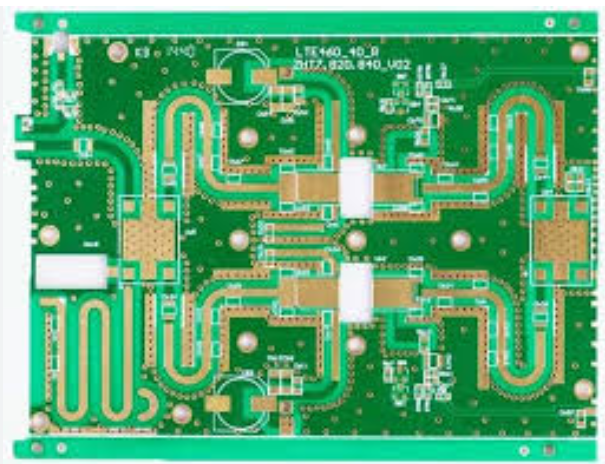
High-frequency PCBs operate at frequencies typically above 1 GHz, where signal integrity and thermal stability are crucial. Unlike conventional PCBs, high-frequency designs involve complex electromagnetic (EM) interactions that generate significant heat. Excessive heat can degrade performance, cause signal loss, and reduce the lifespan of components. Therefore, thermal management must be considered early in the design process.
This paper discusses:
- Heat generation mechanisms in high-frequency PCBs
- Material selection for thermal optimization
- Thermal management techniques
- Simulation and measurement methods
2. Heat Generation Mechanisms in High-Frequency PCBs
Heat in high-frequency PCBs primarily originates from three sources:
2.1 Dielectric Losses
High-frequency signals induce polarization in the dielectric material, leading to energy dissipation as heat. The dissipation factor (Df) or loss tangent (tan δ) quantifies this loss. Materials with lower Df, such as Rogers or PTFE-based substrates, minimize dielectric heating.
2.2 Conductor Losses
At high frequencies, the skin effect forces current to flow near the conductor’s surface, increasing resistance and Joule heating. Additionally, surface roughness exacerbates losses by scattering electrons. Using smooth copper and thicker traces can mitigate this effect.
2.3 Component Power Dissipation
Active components (e.g., RF amplifiers, oscillators) generate substantial heat. Poor thermal design can lead to localized hotspots, affecting signal integrity and component reliability.

3. Material Selection for Thermal Management
The choice of PCB materials significantly impacts thermal performance. Key considerations include:
3.1 Substrate Materials
- PTFE (Teflon): Low loss tangent but poor thermal conductivity (~0.25 W/mK).
- Rogers RO4000 Series: Combines low loss with better thermal conductivity (~0.6 W/mK).
- Ceramic-filled Laminates (e.g., Alumina): High thermal conductivity (20-30 W/mK) but higher cost.
3.2 Copper Properties
- Copper Thickness: Thicker copper improves heat spreading.
- Surface Finish: ENIG (Electroless Nickel Immersion Gold) reduces oxidation and improves thermal transfer.
3.3 Thermal Interface Materials (TIMs)
TIMs enhance heat transfer between PCBs and heatsinks. Common options include:
- Thermal pads (~1-5 W/mK)
- Thermal pastes (~3-8 W/mK)
- Graphite sheets (~300-1500 W/mK)
4. Thermal Management Techniques
Effective thermal management strategies include:
4.1 Heat Sinks and Thermal Vias
- Heat Sinks: Attached to high-power components to dissipate heat.
- Thermal Vias: Plated holes that transfer heat from surface layers to inner planes or heatsinks.
4.2 Copper Pour and Planes
Large copper areas act as heat spreaders. Ground planes also help in thermal dissipation.
4.3 Active Cooling Solutions
- Fans: Used in high-power RF systems.
- Liquid Cooling: For extreme heat conditions, such as in radar systems.
4.4 PCB Layout Optimization
- Component Placement: High-power components should be spaced apart.
- Trace Routing: Avoid long, high-current traces that increase resistance.
5. Thermal Simulation and Measurement
5.1 Simulation Tools
- Finite Element Analysis (FEA): ANSYS, COMSOL
- Computational Fluid Dynamics (CFD): FloTHERM, Icepak
- Electro-Thermal Co-Simulation: Combines EM and thermal analysis.
5.2 Measurement Techniques
- Infrared (IR) Thermography: Detects hotspots.
- Thermocouples: Direct temperature measurement.
- Thermal Resistance Analysis: Evaluates heat flow paths.
6. Case Study: Thermal Analysis of a 5G RF PCB
A 5G RF PCB operating at 28 GHz was analyzed using ANSYS HFSS and Icepak. Key findings:
- Dielectric losses contributed to 40% of total heating.
- Thermal vias reduced hotspot temperatures by 15°C.
- A graphite-based TIM improved heat dissipation by 20%.
7. Conclusion
Thermal management is critical in high-frequency PCB design. By selecting appropriate materials, optimizing layouts, and employing advanced cooling techniques, designers can enhance reliability and performance. Future advancements in low-loss dielectrics and embedded cooling technologies will further improve thermal efficiency in high-frequency applications.