Understanding Hard Drive PCBs: The Heart of Data Storage
Introduction
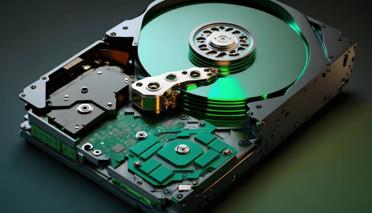
Hard drives have been a cornerstone of data storage for decades, serving as the primary medium for storing and retrieving digital information in computers and other electronic devices. While much attention is often given to the mechanical components of hard drives, such as the platters, read/write heads, and spindle motor, the Printed Circuit Board (PCB) is an equally critical component that often goes unnoticed. The PCB is the electronic backbone of the hard drive, responsible for managing data flow, controlling the mechanical components, and ensuring the drive operates efficiently. This article delves into the intricacies of hard drive PCBs, exploring their design, functionality, common issues, and the role they play in modern data storage.
1. The Role of the PCB in a Hard Drive
The PCB in a hard drive is essentially the control center that bridges the gap between the mechanical components and the computer’s operating system. It is responsible for several key functions:
- Data Transfer: The PCB facilitates the transfer of data between the hard drive and the computer. It converts the analog signals from the read/write heads into digital data that the computer can understand, and vice versa.
- Motor Control: The PCB controls the spindle motor, which spins the platters at a constant speed, typically 5,400, 7,200, or 10,000 revolutions per minute (RPM). It also manages the voice coil motor, which positions the read/write heads accurately over the platters.
- Power Management: The PCB regulates the power supply to the hard drive, ensuring that each component receives the correct voltage and current. This is crucial for maintaining the drive’s stability and longevity.
- Error Correction and Data Integrity: Modern hard drive PCBs are equipped with sophisticated error correction algorithms that detect and correct data errors in real-time. This ensures the integrity of the data stored on the drive.
- Firmware Execution: The PCB contains firmware, which is essentially the hard drive’s operating system. The firmware controls all aspects of the drive’s operation, from initializing the hardware to managing data storage and retrieval.
2. Components of a Hard Drive PCB
A typical hard drive PCB is a complex assembly of various electronic components, each serving a specific function. The main components include:
- Microcontroller (MCU): The MCU is the brain of the PCB, responsible for executing the firmware and controlling all aspects of the hard drive’s operation. It communicates with the computer’s motherboard via the interface connector (e.g., SATA or IDE).
- Read/Write Channel: This component is responsible for processing the analog signals from the read/write heads and converting them into digital data. It also handles the encoding and decoding of data during read and write operations.
- Motor Driver IC: The motor driver IC controls the spindle motor and the voice coil motor. It ensures that the platters spin at the correct speed and that the read/write heads are positioned accurately.
- Flash Memory: The flash memory chip stores the hard drive’s firmware. In some cases, it also stores critical configuration data, such as the drive’s adaptive parameters and defect lists.
- Voltage Regulators: These components regulate the voltage supplied to the various parts of the hard drive, ensuring that each component operates within its specified voltage range.
- Interface Connector: The interface connector (e.g., SATA, IDE, or SCSI) allows the hard drive to communicate with the computer’s motherboard. It is through this connector that data is transferred between the drive and the computer.
- Protection Diodes and Fuses: These components protect the PCB from electrical surges and short circuits, which could otherwise damage the drive.
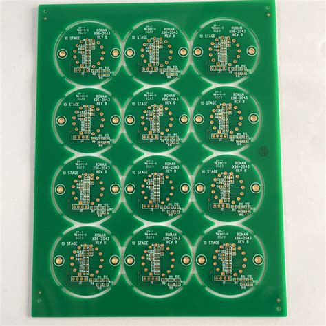
3. PCB Design and Layout
The design and layout of a hard drive PCB are critical to its performance and reliability. The PCB must be designed to minimize electrical noise, ensure signal integrity, and dissipate heat effectively. Key considerations in PCB design include:
- Layer Stackup: Hard drive PCBs are typically multi-layer boards, with each layer serving a specific purpose. The number of layers depends on the complexity of the drive and the required signal integrity. Common layer stackups include 4-layer, 6-layer, and 8-layer boards.
- Signal Integrity: High-speed data transfer requires careful attention to signal integrity. This involves minimizing crosstalk, ensuring proper impedance matching, and reducing electromagnetic interference (EMI).
- Power Distribution: The PCB must distribute power efficiently to all components, ensuring that each component receives the correct voltage and current. This requires careful placement of voltage regulators and decoupling capacitors.
- Thermal Management: Hard drives generate heat during operation, and the PCB must be designed to dissipate this heat effectively. This may involve the use of thermal vias, heat sinks, and careful placement of heat-generating components.
- Component Placement: The placement of components on the PCB is critical to its performance. Components must be placed to minimize signal path lengths, reduce noise, and ensure efficient power distribution.
4. Common Issues with Hard Drive PCBs
Despite their critical role, hard drive PCBs are not immune to failure. Common issues that can affect the PCB include:
- Electrical Surges: Power surges or spikes can damage the PCB’s components, particularly the voltage regulators and protection diodes. This can lead to complete PCB failure.
- Component Failure: Over time, components on the PCB can fail due to wear and tear, overheating, or manufacturing defects. Common components that fail include the motor driver IC, voltage regulators, and capacitors.
- Corrosion: Exposure to moisture or corrosive environments can cause corrosion on the PCB, leading to poor electrical connections and eventual failure.
- Firmware Corruption: The firmware stored in the flash memory can become corrupted due to electrical issues or software bugs. This can render the hard drive inoperable.
- Physical Damage: Physical damage to the PCB, such as cracks or broken traces, can occur due to mishandling or impact. This can disrupt the electrical connections and cause the drive to fail.
5. Repairing and Replacing Hard Drive PCBs
When a hard drive PCB fails, it is often possible to repair or replace it. However, this process requires specialized knowledge and equipment. Key considerations include:
- PCB Compatibility: Not all PCBs are interchangeable, even for drives of the same model. The PCB must match the specific firmware version, component layout, and drive configuration. Using an incompatible PCB can result in further damage or data loss.
- Firmware Transfer: In many cases, the firmware stored on the original PCB is unique to the drive. Simply replacing the PCB with a new one may not work unless the firmware is transferred from the old PCB to the new one. This requires specialized tools and expertise.
- Component-Level Repair: In some cases, it may be possible to repair the PCB by replacing failed components, such as capacitors or voltage regulators. This requires soldering skills and access to replacement parts.
- Data Recovery: If the PCB failure has resulted in data loss, professional data recovery services may be required to retrieve the data. This often involves transferring the platters to a working drive or using specialized equipment to read the data directly from the platters.
6. The Future of Hard Drive PCBs
As data storage technology continues to evolve, the role of the hard drive PCB is also changing. The rise of solid-state drives (SSDs) has led to a shift away from traditional mechanical hard drives, but PCBs remain a critical component in both types of storage devices. In SSDs, the PCB is responsible for managing the NAND flash memory, controlling data flow, and ensuring data integrity.
In the future, we can expect to see further advancements in PCB technology, including:
- Increased Integration: As components become smaller and more powerful, we can expect to see greater integration of functions on the PCB. This could lead to more compact and efficient designs.
- Improved Thermal Management: As data storage demands increase, so too does the need for effective thermal management. Future PCBs may incorporate advanced cooling solutions, such as embedded heat pipes or liquid cooling.
- Enhanced Data Security: With the growing importance of data security, future PCBs may incorporate hardware-based encryption and security features to protect data from unauthorized access.
- AI and Machine Learning: The integration of AI and machine learning algorithms into hard drive firmware could lead to smarter, more adaptive PCBs that can optimize performance and predict failures before they occur.
Conclusion
The hard drive PCB is a critical component that plays a vital role in the operation of modern data storage devices. From managing data flow to controlling mechanical components, the PCB is the electronic heart of the hard drive. Understanding the design, functionality, and common issues associated with hard drive PCBs is essential for anyone involved in data storage, whether as a user, technician, or engineer. As technology continues to evolve, the PCB will remain a key element in the ongoing quest for faster, more reliable, and more secure data storage solutions.


