What Are PCB Rigid-Flex Boards? A Comprehensive Guide
Printed Circuit Boards (PCBs) are the backbone of modern electronics, enabling the interconnection of electronic components in devices ranging from smartphones to aerospace systems. Among the various types of PCBs, rigid-flex boards (also known as flex-rigid PCBs) stand out due to their unique combination of flexibility and structural integrity.
This article explores what rigid-flex PCBs are, their structure, advantages, applications, and design considerations.
1. Introduction to Rigid-Flex PCBs
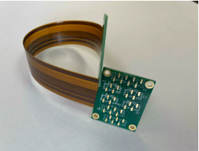
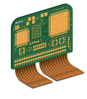
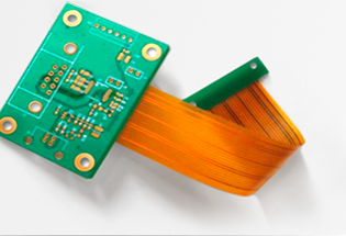
A rigid-flex PCB is a hybrid circuit board that combines rigid and flexible substrates into a single structure. Unlike traditional rigid PCBs or fully flexible circuits, rigid-flex boards integrate both technologies, allowing for three-dimensional (3D) configurations, improved durability, and space-saving designs.
These boards are widely used in industries where compactness, reliability, and dynamic flexing are essential, such as medical devices, aerospace, military systems, and consumer electronics.
2. Structure of Rigid-Flex PCBs
A rigid-flex PCB consists of multiple layers of flexible circuit substrates bonded to rigid board sections. The typical structure includes:
2.1 Flexible Layers
- Made of polyimide (PI) or similar flexible materials.
- Allow bending, folding, and twisting without breaking.
- Used for dynamic flexing areas or to connect rigid sections.
2.2 Rigid Layers
- Made of FR4, high-frequency laminates, or metal-core materials.
- Provide mechanical support for mounting components.
- Used in areas requiring structural stability.
2.3 Adhesive and Coverlay
- Adhesive layers bond flexible and rigid sections.
- Coverlay (flexible solder mask) protects the flexible circuits from environmental damage.
2.4 Plated Through-Holes (PTHs) and Vias
- Ensure electrical connectivity between rigid and flexible layers.
- Can be blind, buried, or through-hole vias depending on design complexity.
3. Advantages of Rigid-Flex PCBs
Rigid-flex PCBs offer several benefits over traditional PCBs:
3.1 Space and Weight Reduction
- Eliminates the need for connectors and cables between rigid boards.
- Enables compact, lightweight designs ideal for portable devices.
3.2 Enhanced Reliability
- Fewer solder joints and connectors reduce failure points.
- Resistant to vibration, shock, and thermal stress.
3.3 Improved Signal Integrity
- Reduced impedance mismatches compared to wired connections.
- Better high-frequency performance due to controlled impedance.
3.4 Design Flexibility
- Can be folded or bent to fit unique enclosures.
- Supports 3D configurations for complex assemblies.
3.5 Cost Efficiency in High-Volume Production
- Although initial costs are higher, long-term savings come from:
- Reduced assembly steps.
- Fewer interconnects.
- Lower maintenance needs.
4. Applications of Rigid-Flex PCBs
Due to their versatility, rigid-flex PCBs are used in high-performance and mission-critical applications:
4.1 Consumer Electronics
- Smartphones & Wearables: Foldable phones, smartwatches.
- Laptops & Tablets: Hinge connections, compact motherboards.
4.2 Medical Devices
- Hearing aids, pacemakers, endoscopes.
- Must withstand repeated flexing and sterilization.
4.3 Aerospace & Defense
- Avionics, satellites, drones.
- Must endure extreme temperatures and vibrations.
4.4 Automotive Industry
- Infotainment systems, sensors, LED lighting.
- Resistant to harsh environments (heat, moisture, vibrations).
4.5 Industrial & Robotics
- Robotic arms, automation controls.
- Requires durability in dynamic movements.
5. Design Considerations for Rigid-Flex PCBs
Designing rigid-flex PCBs requires careful planning to ensure reliability and manufacturability:
5.1 Bend Radius & Flex Life
- Minimum bend radius must be maintained to avoid cracking (typically 6x material thickness).
- Dynamic vs. Static Flexing:
- Dynamic: Frequent bending (e.g., foldable phones).
- Static: Bent once during assembly (e.g., medical implants).
5.2 Layer Stackup & Material Selection
- Choose flexible materials (polyimide) with good thermal stability.
- Ensure compatible adhesives to prevent delamination.
5.3 Trace Routing & Stiffeners
- Avoid sharp angles in flex areas to prevent stress concentration.
- Use stiffeners (FR4, aluminum) in component-heavy areas.
5.4 Thermal Management
- Flexible materials have different CTE (Coefficient of Thermal Expansion) than rigid sections.
- Use thermal vias and heat sinks in high-power areas.
5.5 Manufacturing & Testing Challenges
- Requires specialized PCB fabrication techniques.
- Electrical testing (flying probe, AOI) is critical for reliability.
6. Future Trends in Rigid-Flex PCB Technology
As electronics evolve, rigid-flex PCBs are advancing with:
- Ultra-thin flexible substrates for foldable devices.
- Embedded components within flex layers.
- 3D-printed electronics for rapid prototyping.
- Higher-speed materials for 5G and IoT applications.
7. Conclusion
Rigid-flex PCBs represent a revolutionary approach to circuit design, combining the best of rigid and flexible PCBs. Their space-saving, high-reliability, and 3D-configuration capabilities make them indispensable in modern electronics.
While designing rigid-flex boards requires expertise, the long-term benefits in performance and durability justify their use in cutting-edge applications. As technology progresses, rigid-flex PCBs will continue to enable smaller, smarter, and more robust electronic devices.
Key Takeaway
✅ Rigid-flex PCBs = Rigid + Flexible layers in one board.
✅ Advantages: Lightweight, reliable, space-efficient, better signal integrity.
✅ Applications: Medical, aerospace, automotive, consumer electronics.
✅ Design Tips: Mind the bend radius, material selection, and thermal management.
✅ Future: Thinner flex layers, embedded components, 5G compatibility.
By understanding rigid-flex PCB technology, engineers can unlock new possibilities in miniaturization and high-performance electronics.
Would you like additional details on any specific aspect of rigid-flex PCBs?