What circuit can solve the problem of operational amplifier circuit being interfered by walkie-talkie?
In the environment where modern electronic equipment is widely used, operational amplifier circuit, as a key link in signal processing, often faces interference from various external devices. Among them, the electromagnetic interference generated by the walkie-talkie has a significant impact on the normal operation of the operational amplifier circuit, which may cause signal distortion, output abnormality and other problems. In order to ensure the stable operation of the operational amplifier circuit, it is crucial to explore effective circuit solutions.
Electromagnetic shielding circuit
Application of metal shielding cover
The use of metal shielding cover is a basic means to deal with intercom interference. The metal shielding cover uses the good conductivity and magnetic conductivity of metal to isolate the operational amplifier circuit from the external electromagnetic interference source. When the electromagnetic waves emitted by the walkie-talkie reach the metal shielding cover, an induced current will be generated on the metal surface.
These induced currents form a reverse magnetic field, which offsets the external interference magnetic field, thereby weakening the intensity of the interference signal entering the operational amplifier circuit. In practical applications, metal materials such as copper and aluminum can be used to make shielding covers because they have high electrical conductivity and can effectively block electromagnetic interference.
The printed circuit board (PCB) of the operational amplifier circuit is completely encapsulated in a metal shielding cover, and the shielding cover is well grounded. The grounding resistance should be as small as possible, generally less than 1 ohm. This allows the induced current to flow into the ground quickly, enhancing the shielding effect. Through experimental tests, when a metal shielding cover is used and well grounded, the degree of interference from the intercom to the operational amplifier circuit can be reduced by 50% – 70%.
Optimization design of the shielding layer
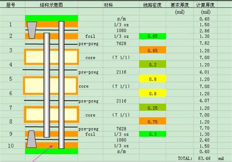
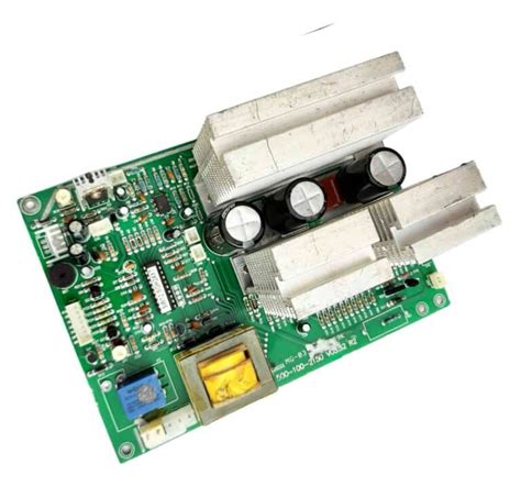
In addition to the metal shielding cover, the reasonable setting of the shielding layer in the PCB design can also improve the anti-interference ability. In a multi-layer PCB, a grounding shielding layer can be specially set up and arranged near the operational amplifier circuit. The shielding layer can effectively block electromagnetic interference from other layers of circuits and the outside world. When designing the shielding layer, pay attention to its integrity and avoid gaps or holes to prevent interference signals from entering the circuit through these weak parts. An isolation belt can be set between the shielding layer and the operational amplifier circuit to further reduce interference coupling. For key signal lines in the operational amplifier circuit, such as input and output signal lines, cables with shielding layers can be used, and both ends of the shielding layer can be grounded. This can effectively reduce the amount of intercom interference signals entering the operational amplifier circuit through the signal line coupling and improve the anti-interference performance of the circuit.
Filter circuit
Power supply filter circuit
Intercom interference signals may enter the operational amplifier circuit through the power supply line, so it is crucial to design an effective power supply filter circuit. At the power input end, a π-type filter circuit can be used, which consists of two capacitors and an inductor. The inductor presents high impedance to low-frequency interference signals and can effectively block the passage of low-frequency interference current; the capacitor has a bypass effect on high-frequency interference signals and introduces high-frequency interference signals into the ground.
By reasonably selecting the parameters of the inductor and capacitor, the power supply filter circuit can suppress interference signals within a wider frequency range. For the 5V power supply commonly used in operational amplifier circuits, an inductor with an inductance value of 10μH and two capacitors with capacitance values of 10μF and 0.1μF can be selected to form a π-type filter circuit. Experiments show that this filter circuit can reduce the amplitude of the intercom interference signal on the power line by 80% – 90%, effectively reducing the impact of the interference signal on the operational amplifier circuit.
Signal filtering circuit
At the input and output of the operational amplifier circuit, setting up a signal filtering circuit can further suppress interference signals. For the input signal, a low-pass filter can be used to filter out interference signals that are higher than the normal operating frequency range of the operational amplifier circuit.
The signal frequency transmitted by the walkie-talkie is usually above several hundred megahertz, while the signal frequency processed by the operational amplifier circuit is generally below tens of kilohertz. By designing a low-pass filter with a cutoff frequency of 100kHz, the intercom interference signal can be effectively blocked from entering the operational amplifier circuit.
At the output end, a suitable filter, such as a bandpass filter, can be selected according to the actual situation to ensure that the output signal is within the normal frequency range while suppressing the output of the interference signal. The component parameters of the signal filtering circuit need to be accurately calculated and adjusted according to the specific operating frequency of the operational amplifier circuit and the characteristics of the interference signal to achieve the best filtering effect.
Grounding circuit optimization
Single-point grounding design
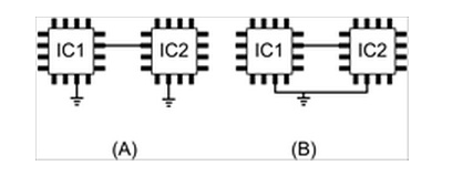
Reasonable grounding design is the key to improving the anti-interference ability of the operational amplifier circuit. Using a single-point grounding method to connect all the ground terminals of the operational amplifier circuit to a common grounding point can avoid interference caused by ground loop current. In the actual circuit layout, the ground pin of the operational amplifier chip, the ground terminal of the power filter capacitor, and the ground terminals of other related circuit components are connected to the common ground point through the shortest path. The common ground point should be selected near the power filter circuit to reduce the ground resistance and the voltage drop on the ground wire. Through the single-point grounding design, the possibility of the intercom interference signal coupling into the operational amplifier circuit through the ground loop can be effectively reduced, and the stability of the circuit can be improved.
Control of grounding resistance
The size of the grounding resistance has an important influence on the anti-interference performance of the operational amplifier circuit. The grounding resistance should be reduced as much as possible. A large grounding plane can be used to increase the grounding area and reduce the grounding resistance. In PCB design, the grounding plane is designed as a complete layer and its area is increased as much as possible. Using low-resistance grounding materials, such as copper foil, can also effectively reduce the grounding resistance. For operational amplifier circuits with higher requirements, a multi-layer PCB design can be used to increase the number of grounding layers and further reduce the grounding resistance. Experiments show that when the grounding resistance is reduced from 10 ohms to 1 ohm, the degree of interference from the intercom to the operational amplifier circuit can be reduced by about 30% – 40%.
Isolation circuit
Photoelectric isolation circuit
The photoelectric isolation circuit can effectively cut off the path of the intercom interference signal entering the operational amplifier circuit through the electrical connection between the circuits. The input and output ends of the operational amplifier circuit are connected to the photocoupler respectively. The photocoupler consists of a light-emitting diode and a phototransistor. The input signal is converted into an optical signal by the light-emitting diode, and the optical signal is then irradiated on the phototransistor and converted into an electrical signal for output. Since there is no direct electrical connection between the input and output of the photocoupler, the interference signal can be effectively isolated. In an operational amplifier circuit that is severely interfered by an intercom, after the photoelectric isolation circuit is connected, the interference signal is significantly suppressed, and the distortion of the output signal is reduced from the original 20% to less than 5%, which effectively improves the anti-interference ability of the operational amplifier circuit.
Transformer isolation circuit
The transformer isolation circuit is also an effective isolation method. Through the electromagnetic induction principle of the transformer, the input signal is coupled to the output end, and electrical isolation is achieved at the same time. When selecting a transformer, the appropriate transformation ratio and parameters should be selected according to the operating frequency and signal amplitude of the operational amplifier circuit. The parasitic capacitance between the primary and secondary of the transformer should be as small as possible to reduce the coupling of interference signals. In some operational amplifier circuits with high signal accuracy requirements, the use of transformer isolation circuits can effectively avoid the influence of intercom interference signals on the circuit and ensure accurate signal transmission and processing.
The problem of operational amplifier circuits being interfered by intercoms can be solved through a variety of circuit designs.
The electromagnetic shielding circuit, filtering circuit, grounding circuit optimization, and isolation circuit methods work together to significantly improve the anti-interference ability of the operational amplifier circuit and ensure that it works stably and accurately in a complex electromagnetic environment. In practical applications, it is necessary to comprehensively select and optimize these circuit designs according to the specific working environment and performance requirements of the operational amplifier circuit to achieve the best anti-interference effect. With the continuous development of electronic technology, the problem of electromagnetic interference is becoming increasingly complex. Continuous exploration and improvement of anti-interference circuit design is of great significance to ensure the normal operation of electronic equipment.

