What is Impedance Matching?
Introduction
Impedance matching is a fundamental concept in electrical engineering, telecommunications, and radio frequency (RF) design. It ensures maximum power transfer between different components of a circuit while minimizing signal reflections. Proper impedance matching is crucial in applications such as audio systems, antennas, transmission lines, and high-frequency circuits.
This article explores the principles of impedance matching, its importance, different techniques used, and practical applications in various fields.
1. Understanding Impedance
Before discussing impedance matching, it is essential to understand what impedance is.
1.1 Definition of Impedance
Impedance (Z) is a measure of opposition to the flow of alternating current (AC) in a circuit. It consists of two components:
- Resistance (R): The real part of impedance, which dissipates energy as heat.
- Reactance (X): The imaginary part, which stores and releases energy (inductive or capacitive).
Impedance is expressed as:
[
Z = R + jX
]
where:
- ( j ) is the imaginary unit (( j^2 = -1 )).
- ( X = X_L – X_C ) (inductive reactance minus capacitive reactance).
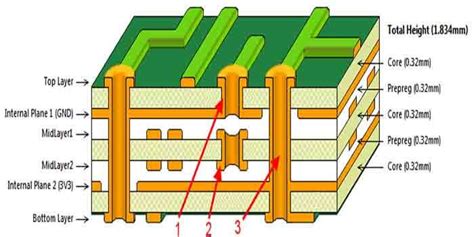
1.2 Characteristic Impedance in Transmission Lines
In transmission lines (e.g., coaxial cables, waveguides), the characteristic impedance (Z₀) is a key parameter. It depends on the line’s physical properties:
[
Z_0 = \sqrt{\frac{R + j\omega L}{G + j\omega C}}
]
where:
- ( R ) = series resistance per unit length
- ( L ) = series inductance per unit length
- ( G ) = shunt conductance per unit length
- ( C ) = shunt capacitance per unit length
- ( \omega ) = angular frequency
For lossless lines (( R = 0, G = 0 )), this simplifies to:
[
Z_0 = \sqrt{\frac{L}{C}}
]
2. The Concept of Impedance Matching
Impedance matching ensures that the output impedance of a source matches the input impedance of the load to maximize power transfer and minimize signal reflections.
2.1 Maximum Power Transfer Theorem
The Maximum Power Transfer Theorem states that maximum power is delivered from a source to a load when the load impedance is the complex conjugate of the source impedance.
For a source impedance ( Z_S = R_S + jX_S ), the load impedance ( Z_L ) should be:
[
Z_L = R_S – jX_S
]
In purely resistive circuits, this simplifies to ( R_L = R_S ).
2.2 Importance of Impedance Matching
- Minimizes Signal Reflections: Mismatched impedances cause reflections, leading to standing waves and signal distortion.
- Improves Efficiency: Ensures maximum power transfer, reducing losses.
- Enhances Signal Integrity: Critical in high-frequency and RF applications.
2.3 Voltage Standing Wave Ratio (VSWR)
VSWR measures impedance mismatch in transmission lines:
[
VSWR = \frac{1 + |\Gamma|}{1 – |\Gamma|}
]
where ( \Gamma ) (reflection coefficient) is:
[
\Gamma = \frac{Z_L – Z_0}{Z_L + Z_0}
]
A VSWR of 1:1 indicates perfect matching.
3. Techniques for Impedance Matching
Several methods are used to achieve impedance matching, depending on frequency and application.
3.1 L-Section Matching (LC Network)
The simplest matching network uses an inductor (L) and capacitor (C) to transform impedance.
- Low-Pass L-Section:
- Series L, Shunt C
- High-Pass L-Section:
- Series C, Shunt L
3.2 Transformer Matching
Transformers can match impedances by adjusting the turns ratio (N):
[
Z_{in} = \left( \frac{N_1}{N_2} \right)^2 Z_L
]
Common in audio systems and RF applications.
3.3 Quarter-Wave Transformer
A transmission line of length ( \lambda/4 ) (quarter wavelength) can match impedances:
[
Z_0 = \sqrt{Z_{in} Z_L}
]
Used in microwave engineering.
3.4 Stub Matching (Open or Shorted Stubs)
A stub (a short section of transmission line) is used to cancel reactance.
- Single Stub: Adjusts impedance by adding a shunt stub.
- Double Stub: Provides more flexibility in tuning.
3.5 T-Network and Pi-Network Matching
More complex than L-sections, these networks provide broader matching ranges:
- T-Network: Two series components with a shunt component in the middle.
- Pi-Network: Two shunt components with a series component in between.
3.6 Active Impedance Matching
Uses active components (transistors, op-amps) for dynamic impedance adjustment.
4. Applications of Impedance Matching
4.1 RF and Antenna Systems
- Ensures efficient power transfer from transmitter to antenna.
- Reduces reflected power, improving signal quality.
4.2 Audio Systems
- Matches speaker impedance to amplifier output for optimal sound quality.
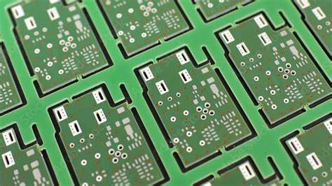
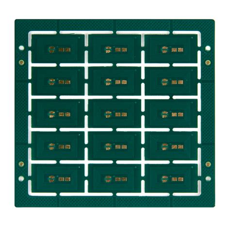
4.3 High-Speed Digital Circuits
- Prevents signal reflections in PCB traces (e.g., DDR memory, USB, HDMI).
4.4 Microwave Engineering
- Used in waveguides, filters, and amplifiers.
4.5 Medical Imaging (Ultrasound)
- Matches transducer impedance to tissue for better imaging.
5. Challenges and Considerations
- Frequency Dependence: Matching networks must operate over desired frequency ranges.
- Component Losses: Real-world components (inductors, capacitors) have parasitic effects.
- Bandwidth Trade-offs: Narrowband vs. broadband matching techniques.
6. Conclusion
Impedance matching is a critical concept in electronics, ensuring efficient power transfer and signal integrity. Various techniques—such as L-sections, transformers, stubs, and quarter-wave transformers—are used depending on the application. Proper impedance matching improves performance in RF systems, audio equipment, high-speed digital circuits, and more.
Understanding and applying impedance matching principles allows engineers to design more efficient and reliable electronic systems.