What is reflection noise?
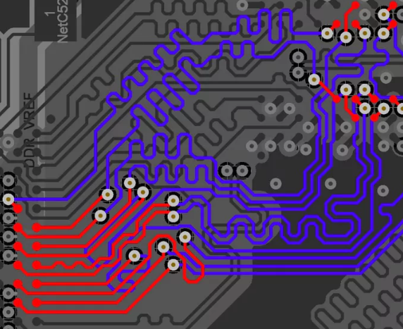
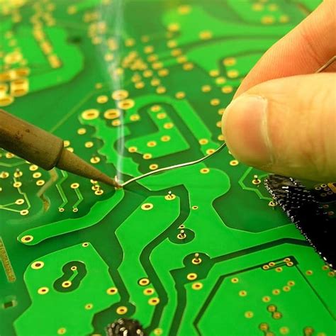
Whenever we send a signal from one digital integrated circuit to another on our PCBS, we change the state of signal line,That change in state and the accompanying changes in electromagnetic fields can be described as wave as it moves through the circuit.Waves are phenomena that transfer energy from one location to another,with conductors guiding the path of propagation.
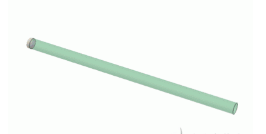
This is an artistic impression of magnetic energy surrounding a wire as the potential of the wire changes.
Reflection noise result when an electromagnetic wave encounters a boundary boundary from one medium to next.When the wave meet the boundary,part of the energy is transmitted as signal and part of it is reflected.
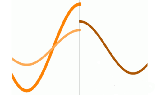
This animation illustrates that,when wave travel from one medium to another,not all energy is transmitted-a portion of the energy is reflected back to its source.
For electrical engineers,the medium where this boundary occurs is usually described in terms of its electrical impedance;that is ,the boundary is where impedance changes.
Impedance is composed of resistive and reactive elements.Resistors dissipate a circuit’s energy as heat.The recoverable energy in a circuit exists in the electromagnetic fields that permeate and surround conductors,inductors, and capacitors.
Whenever the impedance changes in circuit,some amount of reflection will occur.The reflected wave will travel back to the next boundary(the location where there is a change in impedance)and reflect again.
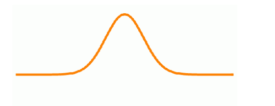
This 1D wave illustration shows a wave pulse reflected between two points.The energy is attenuated over time/distance,
The process will continue indefinitely until the energy is absorbed by the circuit or dissipated into the environment.
Why is reflection nosie a problem?
For signal lines,there will be reflection points at your driver and receiver,The job of the engineer is to minimize the amount of reflected signal and maximize the amount of transmitted signal through impedance matching.
If that is not possible,the additional energy will need to be dissipated before it accumulates and drowns out a signal with noise
If the energy of the reflected pulse does not dissipate before the next pulse is generated,the energy will accumulate and add in a phenomenon called superposition.Fortunately,signals attenuate as they pass through resistive elements.So a simple series resistor will eliminate most ringing.
Assessing Noise in digital signals
Fourier’s theorem teaches that any wave or wave-pulse can be decomposed into a series of sine and/or cosine waves.If you’d like more insight into this concept,I recommend this video on the harmonic analyzer with bill hammack of the university of Illionis.
If you have a sufficiently small rise/fall time ,a single pulse can hold in it dozens of small-amplitude waves.
In the image below, you can see an undamped digital signal switching logic states from low to high.
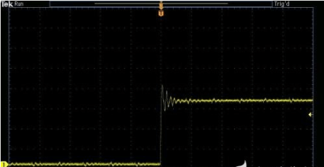
An undamped digital signal(yellow channel 1) captured on a TI lightcrafter as it switches logic states from low to high.
Now check out the image below,where the left-hand image shows a composite wave pulse created through the successive superposition of decreasing amplitude odd-harmonics of the original wave.For signals of practical interest,we can decompose the waveform into a series of sine waves.
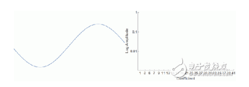
As the above figures show,a real digital signal has a large bandwidth and any portion of that energy might create a resonance in your circuit.This is in contrast to RF signals that have very narrow bandwidth with easy to calculate resonances.
If you do manage to create standing waves,you will create enormous sources of noise that can overwhelm any signal line in the vicinity.
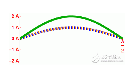
This gif show that wave(orange)reflected at a particular wavelength can combine with its reflection(blue) to create a high amplitude standing wave(green).this phenomenon will happen at odd-integer multiples of 1/2 wavelength,where the wavelength is twice the the length of your trace.