5 Pin PCB Connector: A Comprehensive Guide
Introduction
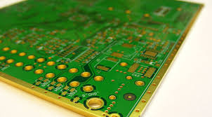
Printed Circuit Board (PCB) connectors are essential components in electronic design, providing reliable connections between PCBs and other devices. Among the various types of PCB connectors, the 5-pin PCB connector is widely used in applications requiring multiple signal or power connections in a compact form factor. This article explores the features, types, applications, advantages, and selection criteria of 5-pin PCB connectors.
1. What is a 5 Pin PCB Connector?
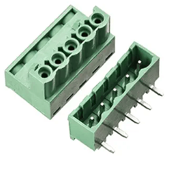
A 5-pin PCB connector is an electrical interconnect component that facilitates the transfer of power and signals between a PCB and external devices. It consists of five conductive pins (male or female) housed in an insulating plastic or metal body. These connectors are designed for through-hole or surface-mount (SMT) soldering onto PCBs, ensuring secure and stable connections.
Key Features:
- 5 conductive pins for multiple connections.
- Compact and space-saving design.
- Available in male (plug) and female (socket) versions.
- Different pitch sizes (e.g., 2.54mm, 3.96mm).
- Materials: High-temperature plastics, metal shielding.
- Current and voltage ratings vary by model.
2. Types of 5 Pin PCB Connectors
5-pin PCB connectors come in various configurations to suit different applications. The most common types include:
A. Wire-to-Board Connectors
- Used to connect wires directly to a PCB.
- Common in automotive, industrial, and consumer electronics.
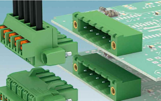
B. Board-to-Board Connectors
- Enable connections between two PCBs (e.g., stacked or parallel configurations).
- Used in modular electronics and embedded systems.
C. Header and Socket Connectors
- Male headers (pins) mate with female sockets.
- Often used in prototyping and development boards (e.g., Arduino, Raspberry Pi).
D. Terminal Block Connectors
- Screw or spring-clamp terminals for secure wire connections.
- Used in power distribution and industrial control systems.
E. Waterproof/Sealed Connectors
- IP-rated for harsh environments (e.g., automotive, marine, outdoor electronics).
3. Applications of 5 Pin PCB Connectors
5-pin PCB connectors are versatile and used across multiple industries:
A. Consumer Electronics
- Smartphones, tablets, and wearables (for internal PCB connections).
- Home appliances (e.g., washing machine control boards).
B. Automotive Electronics
- Engine control units (ECUs), sensors, and infotainment systems.
- LED lighting and battery management systems (BMS).
C. Industrial Automation
- PLCs (Programmable Logic Controllers), motor drivers, and robotics.
- Factory automation and machinery control.
D. Medical Devices
- Patient monitoring systems and diagnostic equipment.
- Portable medical devices requiring reliable interconnects.
E. Telecommunications & Networking
- Routers, switches, and IoT devices.
- Data transmission and signal routing.
4. Advantages of Using 5 Pin PCB Connectors
A. Space Efficiency
- Compact design saves PCB real estate.
B. Reliable Connections
- Secure mating prevents loose connections.
C. Easy Assembly & Replacement
- Simplifies PCB assembly and maintenance.
D. Versatility
- Supports power, signal, and data transmission.
E. Customization Options
- Available in different pitches, orientations (vertical/horizontal), and materials.
5. How to Select the Right 5 Pin PCB Connector?
When choosing a 5-pin PCB connector, consider the following factors:
A. Pitch Size (Pin Spacing)
- Common pitches: 2.54mm (0.1″), 3.96mm, 5.08mm.
- Ensure compatibility with PCB layout.
B. Current & Voltage Rating
- Standard connectors: 1A–5A, 50V–250V.
- High-power applications may require thicker pins.
C. Mounting Type
- Through-hole (THT) for stronger mechanical bonds.
- Surface-mount (SMT) for automated assembly.
D. Mating Cycles (Durability)
- Consumer-grade: 500–1,000 cycles.
- Industrial-grade: 10,000+ cycles.
E. Environmental Resistance
- Temperature range (e.g., -40°C to +105°C).
- Waterproof (IP67/IP68) for outdoor use.
F. Locking Mechanism
- Snap-fit, screw-lock, or latch-based for vibration resistance.
6. Common Issues & Troubleshooting
A. Poor Contact or Intermittent Signals
- Solution: Check for bent pins or contamination; clean contacts.
B. Soldering Defects (Cold Joints, Misalignment)
- Solution: Reflow solder or use a proper stencil for SMT assembly.
C. Mechanical Stress Leading to Broken Pins
- Solution: Use strain relief or reinforced connectors.
D. Overheating Due to High Current
- Solution: Select a higher-rated connector or reduce load.
7. Future Trends in PCB Connectors
- Miniaturization: Smaller pitch sizes (e.g., 1.27mm, 0.8mm).
- High-Speed Data Transmission: USB-C, HDMI, and high-frequency connectors.
- Smart Connectors: Integrated sensors for real-time monitoring.
- Eco-Friendly Materials: Biodegradable plastics and lead-free soldering.
8. Conclusion
The 5-pin PCB connector is a fundamental component in modern electronics, offering flexibility, reliability, and compactness for various applications. Selecting the right connector involves considering pitch, current rating, mounting style, and environmental conditions. As technology advances, we can expect even more efficient and durable connectors to support next-generation electronic devices.
By understanding the different types, applications, and selection criteria, engineers and designers can optimize their PCB layouts for performance and longevity.