Loss solution for PCB wiring in high-speed circuit design
The results of the eye diagram also show that the effect is obvious. In fact, in the process of product design, PCB wiring is often not something you can modify as you want, which involves collaboration between many aspects and departments; changing PCB materials is also very troublesome, and it can only be adjusted after the board is changed. Therefore, sometimes you can change your mind and consider the problem of the path, which may have unexpected results.
Some time ago, we wrote an article about the signal integrity of USB3.0, talking about the selection of one of the components. It happened that a friend encountered a similar problem. Due to excessive loss, he kept adjusting the PCB wiring length, and the length was compressed by 1 inch, but it still didn’t work; he changed the PCB material, but the problem was not solved well. In fact, the problem finally found was the selection of materials, because many times the loss caused by PCB wiring is much smaller than the loss of materials, which many engineers have not noticed. Because many engineers who don’t know much about high-speed circuit design don’t have a clear understanding of component loss, they don’t know where to start, or they think that the PCB wiring is so long and the connector or other components are so small, so they take it for granted that the loss is small…
First, let’s take a rough look at the loss comparison of a common choke, a connector, and a 5-inch PCB wiring (ordinary FR4 material)
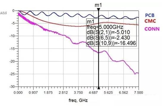
Comparing the 5GHz frequency, it is obvious that the connector has the highest loss, followed by the common choke, and the 5-inch PCB wiring. At this time, if the connector and common choke you choose are relatively poor, no matter how you adjust the PCB wiring, it may not meet your design requirements. Even if you change the material, the effect of reducing the loss will definitely not bring much improvement, compared to its proportion in the loss. But if you can change the common choke or connector, the effect will be obvious. The following is a loss comparison of changing a common choke.
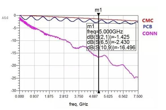
Compared with the 5GHz frequency, the loss of Common choke is greatly reduced, which is completely incomparable to PCB wiring or changing PCB materials. Of course, if the connector is improved, the effect may be more obvious. I will not go into details here. Interested engineers can try it by themselves.
Of course, you can also compare the active eye diagram simulation. Figure 3 is the eye diagram before the device is changed, and Figure 4 is the eye diagram after the device is changed:
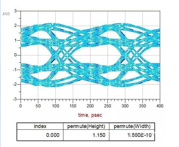
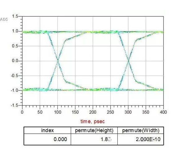
The results of the eye diagram also show that the effect is obvious. In fact, in the process of product design, PCB wiring is often not something you can modify as you want, which involves collaboration between many aspects and departments; changing PCB materials is also very troublesome, and it can only be adjusted after the board is changed. Therefore, sometimes you can change your mind and consider the problem of the path. At this time, there may be unexpected results.