Metal core pcb stackup
Benefits Of Metal Core PCB Stackup In High-Power Applications
Metal core printed circuit boards (PCBs) have become increasingly popular in high-power applications due to their unique benefits. These PCBs incorporate a metal core, typically aluminum or copper, which provides superior thermal management compared to traditional fiberglass-based PCBs. The metal core acts as a heat sink, efficiently dissipating heat away from critical components, thereby enhancing the overall performance and reliability of electronic devices.
One of the primary advantages of metal core PCB stackup in high-power applications is its exceptional thermal conductivity.
Traditional PCBs often struggle with heat dissipation, leading to overheating and potential failure of electronic components. In contrast, the metal core in these PCBs ensures that heat is rapidly conducted away from heat-generating components, maintaining optimal operating temperatures. This is particularly crucial in high-power applications where excessive heat can compromise the functionality and longevity of the device.
Moreover, the enhanced thermal management provided by metal core PCBs allows for higher power densities.
As electronic devices become more compact and powerful, the need for efficient heat dissipation becomes paramount. Metal core PCBs enable designers to pack more components into a smaller space without the risk of overheating. This results in more efficient and powerful devices, meeting the demands of modern high-power applications.
In addition to thermal management, metal core PCBs offer improved mechanical stability.
The metal core provides a robust foundation, reducing the risk of warping or bending under high thermal stress. This stability is essential in high-power applications where devices are subjected to extreme temperatures and mechanical forces. The durability of metal core PCBs ensures that electronic devices can withstand harsh operating conditions, enhancing their reliability and lifespan.
Furthermore, metal core PCBs exhibit excellent electrical insulation properties.
The metal core is typically coated with a dielectric layer, which provides electrical isolation between the conductive layers and the metal core. This insulation is crucial in high-power applications to prevent electrical shorts and ensure the safe operation of the device. The combination of thermal conductivity and electrical insulation makes metal core PCBs an ideal choice for high-power applications where both heat dissipation and electrical safety are paramount.
Another significant benefit of metal core PCB stackup is its compatibility with surface mount technology (SMT).
SMT is widely used in modern electronics manufacturing due to its efficiency and cost-effectiveness. Metal core PCBs can be easily integrated into SMT processes, allowing for seamless assembly and soldering of components. This compatibility streamlines the manufacturing process, reducing production time and costs while maintaining high-quality standards.
Additionally, metal core PCBs are highly customizable, offering flexibility in design and application.
The metal core can be tailored to specific requirements, such as thickness and material composition, to meet the unique needs of different high-power applications. This customization ensures that the PCB can handle the specific thermal and mechanical demands of the device, optimizing its performance and reliability.
In conclusion, the benefits of metal core PCB stackup in high-power applications are manifold. The superior thermal conductivity, mechanical stability, electrical insulation, and compatibility with modern manufacturing processes make metal core PCBs an indispensable component in the design and production of high-power electronic devices. As technology continues to advance, the demand for efficient and reliable thermal management solutions will only grow, solidifying the importance of metal core PCBs in the future of high-power applications.
Design Considerations For Metal Core PCB Stackup
When designing a metal core printed circuit board (MCPCB) stackup, several critical considerations must be taken into account to ensure optimal performance and reliability. The unique properties of MCPCBs, such as their enhanced thermal management capabilities, make them particularly suitable for high-power and high-temperature applications. However, these same properties necessitate a meticulous approach to design.
To begin with, the choice of materials is paramount.
The core material, typically aluminum or copper, plays a crucial role in heat dissipation. Aluminum is often preferred due to its balance of thermal conductivity, weight, and cost. Copper, while offering superior thermal conductivity, is heavier and more expensive. The selection of the core material should align with the specific thermal requirements and budget constraints of the project.
Next, the dielectric layer, which insulates the conductive layers from the metal core, must be carefully selected.
This layer should possess high thermal conductivity to facilitate efficient heat transfer from the components to the metal core. Additionally, it should have a low thermal resistance to minimize heat buildup. Common materials for the dielectric layer include epoxy-based pre-pregs and thermally conductive polymers. The thickness of this layer is also a critical factor; it must be optimized to balance electrical insulation and thermal performance.
The copper foil used for the conductive layers is another important consideration.
The thickness of the copper foil impacts both the current-carrying capacity and the thermal performance of the PCB. Thicker copper foils can handle higher currents and dissipate more heat, but they also increase the overall weight and cost of the PCB. Therefore, the copper thickness should be chosen based on the electrical and thermal demands of the application.
Layer stackup configuration is another crucial aspect of MCPCB design.
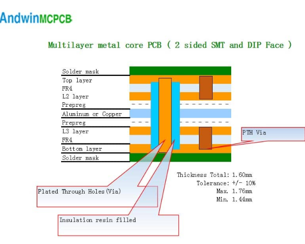
A typical MCPCB stackup consists of a metal core, a dielectric layer, and one or more copper layers. The arrangement and number of these layers depend on the complexity of the circuit and the thermal management requirements. For instance, a single-layer MCPCB might suffice for simple applications with moderate thermal loads, while multi-layer MCPCBs are necessary for more complex circuits with higher thermal demands.
Thermal vias are often incorporated into the design to enhance heat dissipatio
These vias provide a direct thermal path from the heat-generating components to the metal core. The placement and size of thermal vias should be carefully planned to maximize their effectiveness without compromising the electrical performance of the PCB. Additionally, the use of thermal pads and heat sinks can further improve thermal management.
Electrical performance is another critical consideration.
The design must ensure that signal integrity is maintained, especially in high-frequency applications. This involves careful routing of signal traces, proper grounding, and minimizing electromagnetic interference (EMI). The dielectric constant and loss tangent of the insulating materials should be considered to ensure minimal signal degradation.
Manufacturability and cost are also important factors.
The design should be optimized for ease of manufacturing to reduce production costs and improve yield. This includes considering the capabilities and limitations of the fabrication process, such as the minimum trace width and spacing, drilling capabilities, and the ability to handle thick copper layers.
In conclusion, designing a metal core PCB stackup requires a comprehensive understanding of thermal management, material properties, electrical performance, and manufacturability. By carefully considering these factors, designers can create MCPCBs that meet the stringent demands of high-power and high-temperature applications, ensuring both reliability and efficiency.
Thermal Management Solutions Using Metal Core PCB Stackup
Metal core printed circuit boards (MCPCBs) have emerged as a pivotal solution in the realm of thermal management for electronic devices. As electronic components become increasingly powerful and compact, the need for efficient heat dissipation mechanisms has never been more critical. MCPCBs, with their unique stackup configurations, offer a robust solution to this challenge, ensuring the longevity and reliability of electronic systems.
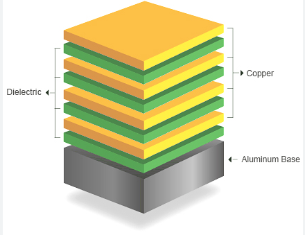
The fundamental structure of an MCPCB involves a metal core, typically aluminum or copper, which serves as the primary heat-conducting layer.
This metal core is sandwiched between dielectric layers and copper circuitry, creating a stackup that effectively manages thermal loads. The choice of metal core material is crucial, as it directly influences the thermal conductivity and mechanical stability of the PCB. Aluminum, for instance, is favored for its lightweight properties and adequate thermal performance, while copper is chosen for applications requiring superior thermal conductivity.
Transitioning to the dielectric layer, this component plays a vital role in electrically isolating the metal core from the copper circuitry.
The dielectric material must possess high thermal conductivity to facilitate efficient heat transfer from the heat-generating components to the metal core. Commonly used dielectric materials include thermally conductive epoxies and ceramics, which are selected based on their thermal and electrical properties. The thickness of the dielectric layer is also a critical parameter, as it impacts the overall thermal resistance of the MCPCB stackup.
Furthermore, the copper circuitry layer is meticulously designed to ensure optimal electrical performance while contributing to the thermal management capabilities of the MCPCB.
The copper traces and pads are strategically placed to minimize thermal resistance and enhance heat dissipation. In high-power applications, thicker copper layers are employed to handle higher current loads and improve thermal performance. The integration of thermal vias, which are plated through holes that connect the copper layers to the metal core, further enhances the heat transfer efficiency.
In addition to the intrinsic thermal management properties of the MCPCB stackup, the design and layout of the PCB play a significant role in optimizing thermal performance.
Proper component placement, the use of thermal relief pads, and the implementation of heat sinks are essential design considerations. By strategically placing heat-generating components near thermal vias and ensuring adequate spacing between components, designers can significantly reduce thermal hotspots and improve overall heat dissipation.
Moreover, the application of MCPCBs extends beyond traditional electronic devices to include high-power LED lighting, automotive electronics, and power supplies. In LED lighting, for instance, the efficient thermal management provided by MCPCBs ensures consistent light output and prolongs the lifespan of the LEDs. Similarly, in automotive electronics, where reliability and performance are paramount, MCPCBs offer a robust solution to manage the thermal loads generated by high-power components.
In conclusion, the metal core PCB stackup represents a sophisticated and effective approach to thermal management in modern electronic systems. By leveraging the thermal conductivity of metal cores, the insulating properties of dielectric layers, and the electrical performance of copper circuitry, MCPCBs provide a comprehensive solution to the challenges posed by high-power and high-density electronic components. As technology continues to advance, the importance of efficient thermal management will only grow, solidifying the role of MCPCBs as a cornerstone in the design and development of reliable electronic systems.
Comparing Metal Core PCB Stackup To Traditional PCB Stackup
When comparing metal core PCB stackup to traditional PCB stackup, it is essential to understand the fundamental differences and advantages each type offers. Metal core printed circuit boards (MCPCBs) are designed with a metal substrate, typically aluminum or copper, which serves as the core material. This metal core provides superior thermal conductivity, making MCPCBs particularly suitable for applications that generate significant heat, such as LED lighting, power supplies, and automotive electronics. In contrast, traditional PCBs are typically constructed with a fiberglass-reinforced epoxy laminate, known as FR4, which does not offer the same level of thermal management.
One of the primary distinctions between metal core PCB stackup and traditional PCB stackup lies in their thermal performance.
The metal core in MCPCBs acts as a heat sink, efficiently dissipating heat away from critical components. This enhanced thermal management capability helps to maintain the reliability and longevity of electronic devices by preventing overheating and thermal stress. Traditional PCBs, on the other hand, rely on thermal vias and copper planes to manage heat, which may not be as effective in high-power applications.
Another significant difference is the mechanical stability provided by the metal core.
MCPCBs exhibit greater rigidity and durability compared to their FR4 counterparts. This robustness makes them ideal for use in environments subject to mechanical stress or vibration. Traditional PCBs, while versatile and widely used, may require additional reinforcement or support in such demanding conditions.
The electrical performance of metal core PCBs also differs from that of traditional PCBs.
The metal core can influence the overall impedance and signal integrity of the circuit. Designers must carefully consider these factors when developing MCPCBs to ensure optimal performance. In contrast, traditional PCBs offer more predictable electrical characteristics, making them suitable for a wide range of applications without the need for extensive customization.
Manufacturing processes for metal core PCBs and traditional PCBs also vary.
The presence of a metal core necessitates specialized fabrication techniques, such as drilling and routing, to accommodate the unique properties of the material. These processes can be more complex and costly compared to the standard methods used for traditional PCBs. However, the benefits of improved thermal management and mechanical stability often justify the additional expense for specific applications.
Furthermore, the choice of materials in the stackup plays a crucial role in the overall performance of the PCB.
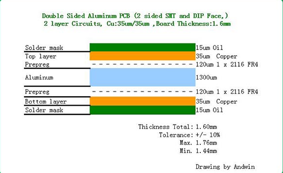
In MCPCBs, the metal core is typically sandwiched between layers of dielectric material and copper foil. The dielectric material must possess high thermal conductivity and electrical insulation properties to ensure efficient heat transfer and electrical isolation. In traditional PCBs, the stackup consists of alternating layers of FR4 and copper, which provide a balance of electrical performance and mechanical strength.
In conclusion, while both metal core PCB stackup and traditional PCB stackup have their respective advantages, the choice between the two depends largely on the specific requirements of the application. Metal core PCBs offer superior thermal management, mechanical stability, and are well-suited for high-power and high-heat environments. Traditional PCBs, with their predictable electrical performance and versatile applications, remain a popular choice for a wide range of electronic devices. Understanding the differences and benefits of each type of PCB stackup is crucial for designers and engineers to make informed decisions that optimize the performance and reliability of their electronic products.