Flex pcb design in kicad
Introduction To Flex PCB Design In KiCad
Flex PCB design has become increasingly popular in the electronics industry due to its ability to provide flexible, lightweight, and compact solutions for complex electronic circuits. KiCad, an open-source software suite for electronic design automation (EDA), offers a robust platform for designing flexible printed circuit boards (PCBs).
This article provides an introduction to flex PCB design in KiCad, highlighting the essential features and steps involved in creating a successful flex PCB project.
To begin with, it is important to understand the fundamental differences between rigid and flexible PCBs.
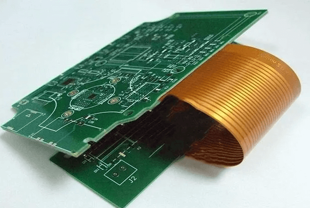
While rigid PCBs are made from solid, inflexible materials, flex PCBs are constructed using flexible substrates such as polyimide. This flexibility allows the PCB to bend and conform to various shapes, making it ideal for applications where space constraints and mechanical stress are significant considerations. Consequently, designing flex PCBs requires careful attention to material properties, mechanical constraints, and electrical performance.
KiCad offers a comprehensive suite of tools that facilitate the design of both rigid and flexible PCBs.
The first step in designing a flex PCB in KiCad is to create a schematic diagram using the Eeschema tool. This involves placing and connecting electronic components, such as resistors, capacitors, and integrated circuits, to form the desired circuit. It is crucial to ensure that the schematic accurately represents the electrical connections and component placements, as any errors at this stage can lead to issues in the final PCB design.
Once the schematic is complete, the next step is to create the PCB layout using the Pcbnew tool.
This involves defining the board outline, placing components, and routing the electrical connections. For flex PCBs, it is essential to consider the mechanical properties of the flexible substrate. This includes defining bend areas, specifying the minimum bend radius, and ensuring that components and traces are placed in a manner that minimizes mechanical stress. KiCad provides various features, such as custom layer stack-ups and design rule checks, to help designers address these considerations.
In addition to the standard PCB design features, KiCad also supports advanced capabilities that are particularly useful for flex PCB design.
For instance, the software allows for the creation of complex board shapes and the use of multiple layers, which can be essential for achieving the desired flexibility and functionality. Furthermore, KiCad’s 3D viewer enables designers to visualize the final PCB in three dimensions, providing a valuable tool for assessing the mechanical fit and ensuring that the design meets the required specifications.
Another critical aspect of flex PCB design is the selection of appropriate materials and manufacturing processes.
Flex PCBs typically use polyimide as the substrate material due to its excellent thermal stability, mechanical strength, and flexibility. Additionally, the choice of adhesive and coverlay materials can significantly impact the performance and reliability of the final product. KiCad’s extensive library of components and materials can assist designers in selecting the appropriate elements for their specific application.
Finally, it is essential to perform thorough testing and validation of the flex PCB design before proceeding to manufacturing.
This includes conducting electrical simulations, mechanical stress analysis, and prototype testing to ensure that the design meets all performance and reliability requirements. KiCad’s integration with various simulation and analysis tools can facilitate this process, enabling designers to identify and address potential issues early in the design cycle.
In conclusion, flex PCB design in KiCad offers a powerful and versatile solution for creating flexible electronic circuits. By leveraging KiCad’s comprehensive suite of tools and features, designers can effectively address the unique challenges associated with flex PCBs, ensuring that their designs are both functional and reliable. As the demand for flexible electronics continues to grow, mastering flex PCB design in KiCad will become an increasingly valuable skill for engineers and designers in the electronics industry.
Best Practices For Flex PCB Layout In KiCad
When designing flexible printed circuit boards (flex PCBs) in KiCad, adhering to best practices is essential to ensure both functionality and durability.
Flex PCBs offer unique advantages, such as the ability to bend and twist, making them ideal for applications where space constraints and mechanical flexibility are critical. However, these benefits come with specific design challenges that must be addressed to achieve optimal performance.
To begin with, understanding the material properties of flex PCBs is crucial.
Unlike rigid PCBs, flex PCBs are made from flexible substrates such as polyimide, which can withstand bending and flexing. This material choice impacts the design rules and constraints that must be followed. For instance, the minimum bend radius is a critical parameter that dictates how tightly the flex PCB can be bent without causing damage. In KiCad, designers should ensure that the layout adheres to the manufacturer’s specifications for bend radius to prevent mechanical failure.
Transitioning to the layout process, it is important to consider the placement of components and traces.
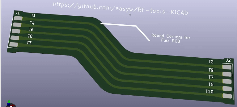
Components should be placed in areas that experience minimal bending to avoid stress on solder joints. Additionally, traces should be routed with smooth, curved paths rather than sharp angles. Sharp angles can create stress points that may lead to cracking or delamination over time. KiCad’s routing tools can be used to create these smooth trace paths, ensuring a more reliable design.
Another key aspect of flex PCB design is the use of teardrops at via and pad connections.
Teardrops are small, tapered extensions that connect traces to pads or vias, providing additional mechanical support and reducing the risk of trace lifting. In KiCad, teardrops can be added manually or through the use of plugins, enhancing the robustness of the design.
Furthermore, it is advisable to use hatched copper fills instead of solid fills for ground and power planes.
Hatched fills provide better flexibility and reduce the risk of cracking compared to solid fills. KiCad allows designers to create hatched fills by adjusting the fill settings in the PCB editor. This practice not only improves mechanical reliability but also maintains electrical performance.
Thermal management is another critical consideration in flex PCB design.
Flexible substrates typically have lower thermal conductivity than rigid materials, making heat dissipation more challenging. To address this, designers should ensure adequate spacing between heat-generating components and use thermal vias to facilitate heat transfer. KiCad’s thermal relief settings can be adjusted to optimize heat dissipation, ensuring that the flex PCB operates within safe temperature limits.
Signal integrity is equally important in flex PCB design.
The flexible nature of the substrate can introduce signal integrity issues, such as impedance variations and crosstalk. To mitigate these issues, designers should carefully control trace impedance and maintain consistent trace widths and spacing. KiCad’s design rule checker (DRC) can be used to verify that the layout meets the required impedance and spacing specifications, ensuring reliable signal transmission.
In conclusion, designing flex PCBs in KiCad requires careful consideration of material properties, component placement, trace routing, mechanical support, thermal management, and signal integrity. By following these best practices, designers can create flexible circuits that are both reliable and efficient. KiCad’s comprehensive set of tools and features provides the necessary support to implement these practices effectively, resulting in high-quality flex PCB designs.
Advanced Techniques For Flex PCB Routing In KiCad
Designing flexible printed circuit boards (PCBs) in KiCad requires a nuanced understanding of both the software and the unique characteristics of flex PCBs. Flex PCBs, known for their ability to bend and twist, are increasingly used in applications where space constraints and mechanical flexibility are paramount. To achieve optimal results, advanced routing techniques must be employed, ensuring both functionality and reliability.
To begin with, it is essential to understand the material properties and mechanical constraints of flex PCBs.
Unlike rigid PCBs, flex circuits are made from flexible substrates such as polyimide, which can endure bending and flexing. This inherent flexibility necessitates careful consideration of trace routing to prevent mechanical stress and potential failure. In KiCad, designers can leverage the software’s robust toolset to address these challenges effectively.
One of the primary considerations in flex PCB design is the minimization of stress on the traces.
To achieve this, it is advisable to use curved traces instead of sharp angles. Sharp angles can act as stress concentrators, leading to potential cracking or delamination over time. KiCad’s interactive router allows for the creation of smooth, curved traces, which distribute mechanical stress more evenly. By selecting the appropriate routing mode and adjusting the trace width, designers can ensure that the traces are both mechanically robust and electrically efficient.
Another critical aspect is the stack-up configuration.
Flex PCBs often consist of multiple layers, including rigid sections for component mounting and flexible sections for interconnections. KiCad’s layer management tools enable designers to define and visualize these different regions accurately. By setting up the stack-up correctly, designers can ensure that the flexible sections have the necessary mechanical properties while maintaining electrical performance. Additionally, the use of stiffeners in rigid-flex designs can provide additional support and prevent excessive bending in critical areas.
Transitioning from rigid to flexible sections requires careful planning.
The bend radius is a crucial parameter that dictates how tightly the flex PCB can be bent without causing damage. KiCad allows designers to specify the bend radius and visualize the bending regions, ensuring that the design adheres to the manufacturer’s specifications. By incorporating these parameters early in the design process, potential issues can be mitigated before fabrication.
Furthermore, the placement of components and vias in flex PCBs demands meticulous attention.
Components should be placed in rigid sections whenever possible to avoid mechanical stress during bending. When placing components in flexible sections is unavoidable, it is essential to use appropriate reinforcement techniques, such as adhesive-backed stiffeners or encapsulation. KiCad’s footprint editor and 3D viewer provide valuable tools for verifying component placement and ensuring that the design meets mechanical constraints.
Signal integrity is another vital consideration in flex PCB design.
The varying dielectric properties of flexible substrates can affect signal propagation, leading to potential issues such as crosstalk and impedance mismatches. KiCad’s simulation tools, including the integrated SPICE simulator, allow designers to analyze and optimize signal integrity. By simulating the electrical performance of the design, potential issues can be identified and addressed before fabrication.
In conclusion, designing flex PCBs in KiCad involves a combination of advanced routing techniques, careful stack-up configuration, and meticulous component placement. By leveraging KiCad’s comprehensive toolset and adhering to best practices, designers can create reliable and efficient flex PCBs that meet the demands of modern applications. Through thoughtful planning and attention to detail, the unique challenges of flex PCB design can be effectively managed, resulting in robust and high-performance circuits.

Troubleshooting Common Issues In Flex PCB Design Using KiCad
Flex PCB design in KiCad offers a versatile and cost-effective solution for creating flexible printed circuit boards, which are essential in various modern electronic applications. However, like any design process, it comes with its own set of challenges. Troubleshooting common issues in flex PCB design using KiCad requires a methodical approach to ensure the final product meets all necessary specifications and functions as intended.
One of the primary issues designers encounter is the proper handling of the flexible substrate.
Unlike rigid PCBs, flex PCBs must account for the mechanical stresses and strains they will endure during operation. To address this, it is crucial to use KiCad’s design rules and constraints effectively. Ensuring that the bend radius is within acceptable limits is vital. A common mistake is to overlook the minimum bend radius, which can lead to cracks and breaks in the conductive traces. By setting appropriate design rules in KiCad, designers can prevent such mechanical failures.
Another frequent problem is the alignment and placement of components on the flex PCB.
Misalignment can lead to poor electrical performance and mechanical issues. KiCad’s footprint editor and layout tools are instrumental in mitigating this problem. By carefully placing components and using the alignment tools provided, designers can ensure that all elements are correctly positioned. Additionally, using the 3D viewer in KiCad can help visualize the final product and identify any potential misalignments before manufacturing.
Signal integrity is another critical aspect that can pose challenges in flex PCB design.
The flexible nature of the board can introduce noise and signal degradation if not properly managed. To troubleshoot this, designers should pay close attention to trace routing and impedance control. KiCad’s differential pair routing and controlled impedance features are beneficial in maintaining signal integrity. By using these tools, designers can ensure that high-speed signals are routed correctly, minimizing the risk of signal loss and interference.
Thermal management is also a significant concern in flex PCB design.
The flexible substrate can have different thermal properties compared to rigid boards, which can affect heat dissipation. Inadequate thermal management can lead to overheating and potential failure of the PCB. KiCad’s thermal analysis tools can help designers identify hotspots and optimize the placement of thermal vias and heat sinks. By conducting thorough thermal simulations, designers can ensure that the flex PCB operates within safe temperature ranges.
Furthermore, manufacturing tolerances and material properties must be considered during the design phase.
Flex PCBs often require precise manufacturing processes, and any deviation can result in defects. KiCad’s design rule check (DRC) and electrical rule check (ERC) features are essential in identifying potential issues before production. By running these checks, designers can catch errors related to trace width, spacing, and other critical parameters, ensuring that the design adheres to manufacturing capabilities.
Lastly, communication with the manufacturer is crucial in troubleshooting flex PCB design issues.
Providing detailed documentation and clear design files can prevent misunderstandings and errors during production. KiCad’s comprehensive documentation tools allow designers to generate detailed fabrication and assembly drawings, which can be shared with the manufacturer to ensure accurate production.
In conclusion, troubleshooting common issues in flex PCB design using KiCad involves a combination of careful planning, effective use of design tools, and thorough validation. By addressing mechanical stresses, component alignment, signal integrity, thermal management, and manufacturing tolerances, designers can create reliable and high-performance flex PCBs. Leveraging KiCad’s robust features and maintaining clear communication with manufacturers are key steps in overcoming the challenges associated with flex PCB design.

