Pcb assembly drawing
Importance Of Accurate PCB Assembly Drawings In Manufacturing
In the realm of electronics manufacturing, the significance of accurate PCB assembly drawings cannot be overstated. These drawings serve as the blueprint for assembling printed circuit boards (PCBs), which are the backbone of virtually all electronic devices.
The precision and clarity of these drawings directly impact the efficiency, quality, and reliability of the final product. Therefore, understanding the importance of accurate PCB assembly drawings is crucial for manufacturers aiming to maintain high standards and meet industry demands.
To begin with, accurate PCB assembly drawings provide a comprehensive visual representation of the PCB layout,
including the placement of components, traces, and connections. This detailed depiction ensures that every element is correctly positioned, which is essential for the functionality of the circuit. Any discrepancies or errors in the drawings can lead to misplacement of components, resulting in malfunctioning devices or complete failure of the circuit. Consequently, meticulous attention to detail in creating these drawings is imperative to avoid costly mistakes and rework.
Moreover, these drawings serve as a critical communication tool between the design and manufacturing teams.
They bridge the gap between conceptual design and physical assembly, ensuring that the manufacturer’s interpretation aligns with the designer’s intent. Clear and precise drawings eliminate ambiguities, reducing the likelihood of miscommunication and errors during the assembly process. This seamless communication is vital for maintaining the integrity of the design and ensuring that the final product meets the specified requirements.
In addition to facilitating communication, accurate PCB assembly drawings also play a pivotal role in quality control.
They provide a reference point for inspecting and verifying the assembled PCBs, ensuring that each component is correctly placed and soldered. By adhering to these drawings, manufacturers can identify and rectify any deviations from the design specifications, thereby enhancing the overall quality and reliability of the product. This rigorous quality control process is essential for meeting industry standards and customer expectations.
Furthermore, accurate PCB assembly drawings contribute to the efficiency and speed of the manufacturing process.
They provide clear instructions for the assembly line workers, enabling them to perform their tasks with precision and confidence. This clarity reduces the likelihood of errors and rework, thereby streamlining the production process and minimizing downtime. In a competitive market where time-to-market is a critical factor, the efficiency gained from accurate drawings can provide a significant advantage.
Additionally, these drawings are indispensable for troubleshooting and maintenance.
In the event of a malfunction or failure, they serve as a valuable reference for diagnosing and repairing the issue. Accurate drawings enable technicians to quickly identify the problem areas and implement corrective measures, thereby reducing downtime and ensuring the continued operation of the device. This aspect is particularly important for industries where reliability and uptime are paramount, such as aerospace, medical devices, and telecommunications.
In conclusion, the importance of accurate PCB assembly drawings in manufacturing cannot be emphasized enough. They ensure the correct placement of components, facilitate clear communication between design and manufacturing teams, enhance quality control, improve efficiency, and aid in troubleshooting and maintenance. By prioritizing accuracy and precision in these drawings, manufacturers can achieve higher standards of quality, reliability, and efficiency, ultimately leading to greater customer satisfaction and success in the competitive electronics market.

Key Elements To Include In A PCB Assembly Drawing
A PCB assembly drawing is a critical document in the electronics manufacturing process, serving as a blueprint for assembling a printed circuit board (PCB). It provides detailed instructions and specifications necessary for the accurate and efficient assembly of electronic components onto the PCB. To ensure clarity and precision, several key elements must be included in a PCB assembly drawing.
Firstly, the assembly drawing should feature a comprehensive bill of materials (BOM).
The BOM lists all components required for the assembly, including part numbers, descriptions, quantities, and reference designators. This list is essential for procurement and inventory management, ensuring that all necessary components are available for the assembly process. Additionally, the BOM helps in cross-referencing components with their respective locations on the PCB, facilitating accurate placement and reducing the risk of errors.
Next, the drawing must include a detailed component placement diagram.
This diagram visually represents the exact location of each component on the PCB, using reference designators to match components listed in the BOM. It is crucial for the diagram to be clear and legible, with components accurately positioned to avoid confusion during assembly. The placement diagram should also indicate the orientation of polarized components, such as diodes and electrolytic capacitors, to prevent incorrect installation.
Furthermore, the assembly drawing should provide specific assembly notes and instructions.
These notes may include guidelines for soldering techniques, component handling precautions, and any special assembly requirements. For instance, certain components may require specific soldering temperatures or techniques to avoid damage. Including these instructions ensures that the assembly process adheres to the necessary standards and quality requirements.
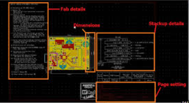
Another essential element is the inclusion of mechanical drawings and dimensions.
These drawings provide precise measurements and tolerances for the PCB and its components, ensuring that everything fits together correctly. Mechanical drawings may also indicate mounting holes, cutouts, and other physical features of the PCB that are critical for proper assembly and integration into the final product.
In addition to mechanical drawings, the assembly drawing should feature a solder mask and paste layer information.
The solder mask layer indicates areas of the PCB that should be covered with solder mask to prevent solder bridging and short circuits. The paste layer, on the other hand, shows where solder paste should be applied for surface-mount components. Accurate representation of these layers is vital for the automated soldering process, ensuring reliable electrical connections.
Moreover, the drawing should include a legend or key to explain any symbols, abbreviations, or notations used.
This legend helps assembly technicians and engineers understand the various elements of the drawing, reducing the likelihood of misinterpretation. Clear and consistent use of symbols and notations is essential for effective communication and efficient assembly.
Lastly, it is important to incorporate quality control and inspection criteria into the assembly drawing.
These criteria outline the standards and procedures for inspecting the assembled PCB, ensuring that it meets the required specifications and performance standards. Including inspection criteria helps maintain high-quality standards and facilitates the identification and correction of any assembly defects.
In conclusion, a well-prepared PCB assembly drawing is indispensable for the successful assembly of electronic components onto a PCB.
By including a comprehensive bill of materials, detailed component placement diagram, specific assembly notes, mechanical drawings, solder mask and paste layer information, a clear legend, and quality control criteria, the drawing provides all the necessary information for accurate and efficient assembly. This meticulous attention to detail ensures that the final product meets the desired quality and performance standards, ultimately contributing to the success of the electronics manufacturing process.
Common Mistakes To Avoid In PCB Assembly Drawings
In the realm of electronics manufacturing, PCB assembly drawings serve as a critical blueprint for the successful creation of printed circuit boards. These drawings provide detailed instructions and specifications that guide the assembly process, ensuring that each component is correctly placed and soldered. However, despite their importance, several common mistakes can compromise the effectiveness of PCB assembly drawings, leading to costly errors and delays. By understanding and avoiding these pitfalls, manufacturers can enhance the accuracy and efficiency of their PCB assembly processes.
One prevalent mistake in PCB assembly drawings is the omission of essential details.
It is crucial to include comprehensive information about each component, such as reference designators, part numbers, and precise placement locations. Without these specifics, assemblers may misinterpret the drawing, resulting in incorrect component placement or orientation. Additionally, it is important to provide clear and unambiguous instructions for any special assembly requirements, such as specific soldering techniques or the use of particular tools. By ensuring that all necessary details are included, manufacturers can minimize the risk of assembly errors and improve overall product quality.
Another common error is the use of unclear or inconsistent symbols and notations.
Standardized symbols and notations are essential for effective communication in PCB assembly drawings. When symbols are ambiguous or inconsistent, it can lead to confusion and misinterpretation among assembly personnel. To avoid this, manufacturers should adhere to industry standards and guidelines for symbols and notations, ensuring that all drawings are clear and easily understood. Consistency in the use of symbols and notations across all drawings is also vital, as it helps maintain uniformity and reduces the likelihood of errors.
Furthermore, inadequate documentation of component orientations is a frequent issue in PCB assembly drawings
Components such as diodes, transistors, and integrated circuits have specific orientation requirements that must be accurately depicted in the drawings. Failing to clearly indicate the correct orientation can result in improper assembly, leading to malfunctioning or damaged components. To prevent this, manufacturers should use clear and distinct markings to indicate component orientations, such as polarity indicators for diodes or pin 1 designations for integrated circuits. Providing visual aids, such as diagrams or photographs, can also be beneficial in ensuring correct component placement.
In addition to these issues, neglecting to include a comprehensive bill of materials (BOM) is another common mistake.
The BOM is a critical component of PCB assembly drawings, as it lists all the parts and materials required for the assembly process. An incomplete or inaccurate BOM can lead to delays and increased costs, as assemblers may need to source missing components or rectify incorrect part numbers. To avoid this, manufacturers should ensure that the BOM is complete, accurate, and up-to-date, reflecting any changes or revisions made during the design process.
Lastly, insufficient attention to design for manufacturability (DFM) considerations can also hinder the effectiveness of PCB assembly drawings.
DFM involves designing PCBs in a way that facilitates efficient and cost-effective manufacturing. This includes considerations such as component spacing, trace routing, and thermal management. Neglecting DFM principles can result in assembly challenges, increased production costs, and reduced product reliability. By incorporating DFM guidelines into the design and assembly drawing process, manufacturers can optimize the manufacturability of their PCBs and enhance overall production efficiency.
In conclusion, avoiding common mistakes in PCB assembly drawings is essential for ensuring accurate and efficient assembly processes. By including comprehensive details, using clear and consistent symbols, accurately documenting component orientations, providing a complete BOM, and adhering to DFM principles, manufacturers can minimize errors and improve the quality and reliability of their PCBs. Through careful attention to these aspects, the effectiveness of PCB assembly drawings can be significantly enhanced, leading to successful and cost-effective electronics manufacturing.
How To Optimize PCB Assembly Drawings For Efficient Production
Optimizing PCB assembly drawings for efficient production is a critical aspect of the electronics manufacturing process. These drawings serve as the blueprint for assembling printed circuit boards (PCBs), and their clarity and accuracy can significantly impact the efficiency and quality of the final product. To achieve this optimization, several key considerations must be taken into account, starting with the importance of detailed and precise documentation.
Firstly, it is essential to ensure that the PCB assembly drawing includes all necessary information.
This encompasses component placement, orientation, and reference designators, which are crucial for accurate assembly. Including a comprehensive bill of materials (BOM) that lists all components, along with their part numbers and descriptions, can further streamline the process. By providing this level of detail, manufacturers can minimize the risk of errors and reduce the time spent cross-referencing information.
In addition to detailed documentation, the use of clear and standardized symbols and notations is paramount.
Standardization helps in avoiding confusion and ensures that all parties involved in the production process interpret the drawings consistently. Adopting industry-standard symbols for components and using consistent labeling conventions can facilitate smoother communication between designers, manufacturers, and quality control teams.
Another important aspect of optimizing PCB assembly drawings is the inclusion of assembly notes and instructions.
These notes should provide specific guidance on assembly techniques, such as soldering methods, component handling precautions, and any special requirements for certain components. By offering explicit instructions, designers can help assembly technicians understand the nuances of the design, thereby reducing the likelihood of assembly errors and rework.
Moreover, the layout of the PCB assembly drawing itself can influence production efficiency.
Organizing the drawing in a logical and easy-to-follow manner can aid in quick comprehension and execution. For instance, grouping related components together and arranging them in a way that mirrors the actual assembly sequence can be highly beneficial. This approach allows assembly technicians to follow a natural progression, which can enhance their workflow and reduce assembly time.
Transitioning to the use of advanced software tools can also play a significant role in optimizing PCB assembly drawings.
Modern CAD (Computer-Aided Design) software offers features that can automate many aspects of the drawing process, such as generating accurate footprints, creating detailed BOMs, and performing design rule checks. These tools can help designers produce more accurate and comprehensive drawings, which in turn can lead to more efficient production.
Furthermore, collaboration and communication between the design and manufacturing teams are crucial for optimizing PCB assembly drawings.
Regular feedback loops and design reviews can help identify potential issues early in the process. By involving manufacturing experts in the design phase, designers can gain valuable insights into manufacturability and assembly challenges, allowing them to make informed decisions that enhance production efficiency.
Lastly, continuous improvement should be a guiding principle in the optimization of PCB assembly drawings. By analyzing production data and gathering feedback from assembly technicians, designers can identify recurring issues and areas for improvement. Implementing changes based on this feedback can lead to incremental enhancements in the drawing process, ultimately resulting in more efficient and reliable PCB assembly.
In conclusion, optimizing PCB assembly drawings for efficient production requires a multifaceted approach that includes detailed documentation, standardized symbols, clear assembly instructions, logical layout, advanced software tools, effective collaboration, and a commitment to continuous improvement. By focusing on these key areas, designers can create assembly drawings that not only facilitate accurate and efficient production but also contribute to the overall quality and reliability of the final product.