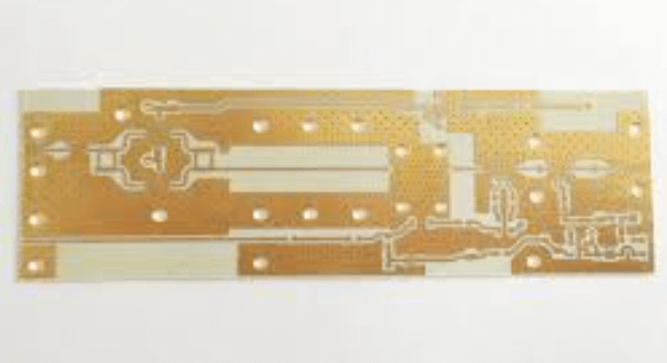
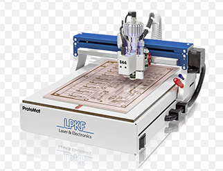
Pcb prototype milling machine
Advantages Of Using A PCB Prototype Milling Machine
A PCB prototype milling machine offers numerous advantages that make it an indispensable tool in the field of electronics design and manufacturing.
One of the primary benefits is the significant reduction in turnaround time.
Traditional methods of PCB prototyping, such as outsourcing to a fabrication house, can take several days or even weeks. In contrast, a PCB prototype milling machine allows engineers to produce a functional prototype within hours. This rapid production capability is particularly advantageous during the iterative design process, where multiple revisions are often necessary to achieve the desired functionality.
Moreover, the use of a PCB prototype milling machine enhances confidentiality and intellectual property protection.
When outsourcing PCB fabrication, there is always a risk of exposing sensitive design information to third parties. By keeping the prototyping process in-house, companies can better safeguard their proprietary designs and maintain control over their intellectual property. This is especially critical for industries where confidentiality is paramount, such as defense, aerospace, and high-tech consumer electronics.
In addition to speed and security, PCB prototype milling machines offer a high degree of precision and accuracy.
Modern milling machines are equipped with advanced software and hardware that enable them to produce intricate and complex PCB designs with minimal errors. This level of precision is essential for creating high-quality prototypes that closely match the final product. Furthermore, the ability to produce accurate prototypes allows engineers to identify and rectify design flaws early in the development process, thereby reducing the likelihood of costly mistakes in mass production.
Another notable advantage is the cost-effectiveness of using a PCB prototype milling machine.
While the initial investment in the equipment may be substantial, the long-term savings can be significant. By eliminating the need for outsourcing and reducing the number of design iterations, companies can save on both time and money. Additionally, the ability to produce prototypes on-demand means that there is no need to order large quantities of PCBs, which can result in excess inventory and wasted resources.
The versatility of PCB prototype milling machines also cannot be overlooked.
These machines are capable of handling a wide range of materials, including various types of copper-clad laminates, which are commonly used in PCB manufacturing. This flexibility allows engineers to experiment with different materials and design configurations, ultimately leading to more innovative and optimized products. Furthermore, the ability to quickly switch between different projects and designs makes the milling machine a valuable asset for research and development teams.
Environmental considerations also play a role in the advantages of PCB prototype milling machines.
Traditional PCB manufacturing processes often involve the use of hazardous chemicals and generate significant waste. In contrast, milling machines produce minimal waste and do not require the use of harmful substances. This makes them a more environmentally friendly option, aligning with the growing emphasis on sustainable and eco-friendly manufacturing practices.
In conclusion, the advantages of using a PCB prototype milling machine are manifold. From reducing turnaround time and enhancing confidentiality to offering precision, cost-effectiveness, versatility, and environmental benefits, these machines are a vital tool for modern electronics design and manufacturing. As technology continues to advance, the capabilities and benefits of PCB prototype milling machines are likely to expand even further, solidifying their role as an essential component in the prototyping process.
Step-By-Step Guide To PCB Prototype Milling
Creating a printed circuit board (PCB) prototype using a milling machine is a meticulous process that requires precision and attention to detail. This step-by-step guide aims to provide a comprehensive overview of the procedure, ensuring that even those new to the field can follow along and achieve satisfactory results.
To begin with, the initial step involves designing the PCB layout using specialized software such as Eagle, KiCad, or Altium Designer. These programs allow for the creation of intricate circuit designs, which can then be exported as Gerber files. Gerber files are the industry standard for PCB manufacturing and contain all the necessary information about the board’s layout, including the copper traces, drill holes, and component placements.
Once the design is finalized and the Gerber files are ready, the next step is to prepare the milling machine.
This involves securing the PCB material, typically a copper-clad board, onto the milling bed. It is crucial to ensure that the board is firmly attached to prevent any movement during the milling process, which could result in inaccuracies. Double-sided tape or vacuum tables are commonly used for this purpose.
Following the setup of the PCB material, the milling machine must be configured with the appropriate settings.
This includes selecting the correct milling bits, which vary in size depending on the intricacy of the design. For instance, finer traces require smaller bits, while larger areas can be milled with bigger bits. Additionally, the spindle speed and feed rate must be adjusted to match the material and bit specifications, ensuring a clean and precise cut.
With the machine configured, the next step is to load the Gerber files into the milling software.
This software translates the design into machine-readable instructions, guiding the milling bit along the specified paths. It is advisable to perform a dry run without the milling bit engaged to verify that the machine follows the correct paths and to identify any potential issues before actual milling begins.
Once the dry run is satisfactory, the milling process can commence.
The machine will meticulously carve out the copper traces, drill holes for component leads, and cut out the board’s outline. It is essential to monitor the process closely, as any deviations or errors can compromise the integrity of the PCB. If any issues arise, pausing the machine and making necessary adjustments can prevent further complications.
After the milling is complete, the next step involves cleaning the PCB to remove any debris or burrs left from the milling process. This can be done using a soft brush or compressed air. Following the cleaning, the board should be inspected for any defects or incomplete traces. If any issues are found, they can often be corrected using a fine-tip soldering iron or conductive ink.
The final step in the PCB prototype milling process is to populate the board with the necessary electronic components.
This involves soldering each component to its designated location on the board, ensuring proper electrical connections. Once all components are in place, the board should be tested to verify that it functions as intended. This may involve using a multimeter to check for continuity and correct voltage levels or performing a functional test with the intended application.
In conclusion, PCB prototype milling is a detailed and precise process that requires careful planning and execution. By following these steps, one can create a functional and reliable PCB prototype, paving the way for further development and eventual production.
Comparing PCB Prototype Milling Machines: Features And Benefits
When comparing PCB prototype milling machines, it is essential to consider the various features and benefits that each model offers. These machines are indispensable tools in the electronics industry, enabling the rapid creation of printed circuit boards (PCBs) for testing and development purposes. As technology advances, the capabilities of these machines have expanded, making it crucial to understand the key aspects that differentiate them.
One of the primary features to evaluate is the precision and accuracy of the milling machine.
High-precision machines are capable of producing intricate and detailed PCB designs, which is particularly important for complex circuits. The accuracy of the milling process directly impacts the functionality and reliability of the final product. Therefore, machines with advanced control systems and high-resolution capabilities are often preferred by professionals who require meticulous detail in their prototypes.
Another significant factor to consider is the speed of the milling process.
In a fast-paced development environment, the ability to quickly produce prototypes can greatly enhance productivity. Machines that offer high-speed milling without compromising on quality are highly valued. This is especially true for iterative design processes where multiple versions of a PCB may need to be tested and refined in a short period.
The versatility of the milling machine is also a critical consideration.
Some machines are designed to handle a wide range of materials, including various types of copper-clad laminates and substrates. This flexibility allows engineers to experiment with different materials to achieve optimal performance for their specific applications. Additionally, machines that support various milling tools and techniques can provide greater adaptability, enabling users to create diverse PCB designs with varying levels of complexity.
Ease of use and user interface are also important aspects to evaluate.
Modern PCB prototype milling machines often come equipped with intuitive software that simplifies the design and milling process. User-friendly interfaces can significantly reduce the learning curve, allowing engineers and designers to focus more on innovation rather than grappling with complex machinery. Furthermore, machines that offer seamless integration with popular PCB design software can streamline the workflow, making it easier to transition from digital design to physical prototype.
Maintenance and durability are other crucial factors to consider.
Machines that are built with high-quality components and robust construction tend to have longer lifespans and require less frequent maintenance. This not only reduces downtime but also lowers the total cost of ownership over time. Additionally, machines that come with comprehensive support and service options can provide peace of mind, ensuring that any issues can be promptly addressed by the manufacturer.
Cost is inevitably a significant consideration when comparing PCB prototype milling machines.
While high-end machines with advanced features may come with a higher price tag, it is important to weigh the benefits they offer against the investment required. In many cases, the increased efficiency, precision, and versatility of a more expensive machine can justify the initial expenditure, especially for businesses that rely heavily on rapid prototyping.
In conclusion, when comparing PCB prototype milling machines, it is essential to consider factors such as precision, speed, versatility, ease of use, maintenance, durability, and cost. By carefully evaluating these features, one can select a machine that best meets their specific needs and enhances their ability to produce high-quality PCB prototypes efficiently. As technology continues to evolve, the capabilities of these machines will likely expand further, offering even greater benefits to the electronics industry.

Common Mistakes To Avoid When Using A PCB Prototype Milling Machine
When utilizing a PCB prototype milling machine, it is crucial to be aware of common mistakes that can compromise the quality of your printed circuit boards and potentially damage the equipment. One frequent error is neglecting to properly secure the material to the milling bed. Ensuring that the PCB material is firmly attached is essential to prevent any movement during the milling process, which can lead to misalignment and inaccurate cuts. Using double-sided tape or a vacuum table can help achieve a stable setup.
Another common mistake is failing to calibrate the milling machine correctly.
Calibration is vital for achieving precise milling depths and accurate trace widths. Before starting any milling operation, it is important to verify that the machine’s settings match the specifications of your design. This includes checking the tool height, spindle speed, and feed rate. Inaccurate calibration can result in uneven traces, incomplete cuts, or even damage to the milling bit.
Additionally, overlooking the importance of selecting the appropriate milling bit for the task at hand can lead to suboptimal results.
Different milling bits are designed for various materials and trace widths. Using the wrong bit can cause excessive wear on the tool, poor-quality cuts, and potential damage to the PCB material. It is advisable to consult the manufacturer’s guidelines or seek expert advice to determine the best bit for your specific application.
Furthermore, improper handling of the milling machine can also lead to errors.
For instance, applying excessive force when changing bits or adjusting the machine can cause misalignment or damage to the equipment. It is important to handle the machine with care and follow the recommended procedures for maintenance and adjustments. Regularly cleaning the machine and ensuring that all moving parts are well-lubricated can also help maintain its performance and longevity.
Another pitfall to avoid is neglecting to perform a test run before milling the actual PCB.
A test run on a scrap piece of material can help identify any potential issues with the machine’s settings or the design itself. This step can save time and resources by allowing you to make necessary adjustments before committing to the final milling process. Skipping this step can result in wasted materials and the need for costly rework.
Moreover, inadequate attention to the design file can lead to milling errors.
Ensuring that the design file is correctly formatted and free of errors is essential for successful milling. This includes verifying that all traces are properly connected, there are no overlapping elements, and the design adheres to the machine’s capabilities. Using design software that is compatible with your milling machine can help streamline this process and reduce the likelihood of errors.
Lastly, failing to consider the limitations of the milling machine can result in unrealistic expectations and unsatisfactory outcomes.
Understanding the machine’s capabilities, such as the minimum trace width and maximum material thickness, is crucial for designing PCBs that can be accurately milled. Pushing the machine beyond its limits can lead to poor-quality boards and potential damage to the equipment.
In conclusion, avoiding these common mistakes when using a PCB prototype milling machine can significantly improve the quality of your printed circuit boards and extend the life of your equipment. By securing the material properly, calibrating the machine accurately, selecting the appropriate milling bit, handling the machine with care, performing test runs, ensuring the design file is error-free, and understanding the machine’s limitations, you can achieve precise and reliable results in your PCB prototyping endeavors.