Rogers 4003c pcb manufacture
Benefits Of Using Rogers 4003C In High-Frequency PCB Applications
Rogers 4003C is a high-frequency laminate material that has garnered significant attention in the field of printed circuit board (PCB) manufacturing. Its unique properties make it an ideal choice for applications that demand superior performance, particularly in high-frequency environments.
One of the primary benefits of using Rogers 4003C in high-frequency PCB applications is its excellent electrical performance.
The material exhibits a low dielectric constant (Dk) and low dissipation factor (Df), which are crucial for maintaining signal integrity and minimizing signal loss. This ensures that high-frequency signals can travel through the PCB with minimal degradation, making it suitable for applications such as RF and microwave circuits, where precision and reliability are paramount.
In addition to its outstanding electrical properties, Rogers 4003C offers exceptional thermal stability.
The material can withstand high temperatures without significant changes in its dielectric properties, which is essential for maintaining consistent performance in demanding environments. This thermal stability also contributes to the longevity and reliability of the PCB, as it reduces the risk of thermal-induced failures. Furthermore, Rogers 4003C is compatible with standard PCB manufacturing processes, which simplifies the production process and reduces costs. Manufacturers can use conventional methods and equipment to fabricate PCBs with Rogers 4003C, eliminating the need for specialized tools or techniques. This compatibility not only streamlines production but also ensures that the material can be easily integrated into existing manufacturing workflows.
Another notable advantage of Rogers 4003C is its mechanical robustness.
The material exhibits excellent dimensional stability, which means it maintains its shape and size even under mechanical stress. This is particularly important in high-frequency applications, where precise dimensions are critical for ensuring optimal performance. The mechanical strength of Rogers 4003C also enhances the durability of the PCB, making it more resistant to physical damage during handling and operation. Moreover, Rogers 4003C is known for its low moisture absorption, which is a significant benefit in environments where humidity and moisture are concerns. Low moisture absorption helps maintain the electrical properties of the material, preventing performance degradation over time. This characteristic is especially valuable in outdoor or harsh environments, where exposure to moisture can be a common issue.
The versatility of Rogers 4003C extends to its compatibility with various types of surface finishes and metallization options.
This flexibility allows designers to choose the most appropriate finish for their specific application, further optimizing the performance and reliability of the PCB. Additionally, the material’s compatibility with different metallization options ensures that it can be used in a wide range of applications, from simple single-layer boards to complex multi-layer designs. In conclusion, the benefits of using Rogers 4003C in high-frequency PCB applications are manifold. Its excellent electrical performance, thermal stability, mechanical robustness, low moisture absorption, and compatibility with standard manufacturing processes make it an ideal choice for demanding applications. By leveraging the unique properties of Rogers 4003C, manufacturers can produce high-frequency PCBs that deliver superior performance, reliability, and durability, meeting the stringent requirements of modern electronic systems.
Step-By-Step Guide To Manufacturing PCBs With Rogers 4003C
Manufacturing printed circuit boards (PCBs) with Rogers 4003C material involves a series of meticulous steps that ensure the final product meets the high-performance standards required in various applications, particularly in high-frequency and microwave circuits.
The process begins with the selection of the Rogers 4003C laminate, known for its excellent electrical properties, low dielectric loss, and stable performance over a wide range of frequencies. This material is chosen for its ability to maintain signal integrity, which is crucial in advanced electronic applications.
The first step in the manufacturing process is the design phase, where engineers create detailed schematics and layout designs using specialized software.
This design includes the placement of components, routing of electrical connections, and the definition of layers. Once the design is finalized, it is converted into a format suitable for manufacturing, typically Gerber files, which contain all the necessary information for each layer of the PCB.
Following the design phase, the next step is the preparation of the Rogers 4003C laminate.
This involves cutting the laminate to the required dimensions and cleaning it to remove any contaminants that could affect the adhesion of the subsequent layers. The cleaned laminate is then coated with a layer of photoresist, a light-sensitive material that will be used to transfer the circuit pattern onto the laminate.
The photoresist-coated laminate is then exposed to ultraviolet (UV) light through a photomask, which contains the circuit pattern.
The UV light hardens the photoresist in the exposed areas, while the unexposed areas remain soft and can be washed away using a developer solution. This process creates a precise pattern of the circuit on the laminate.
Next, the exposed areas of the laminate are etched away using a chemical solution, typically an acid, to remove the unwanted copper and leave behind the desired circuit pattern. After etching, the remaining photoresist is stripped away, revealing the copper traces that form the electrical connections on the PCB.
The subsequent step involves drilling holes for vias and through-hole components.
These holes are drilled using precision machinery to ensure accurate placement and size. Once the holes are drilled, they are plated with copper to create electrical connections between the different layers of the PCB.
Following the drilling and plating process, the PCB undergoes a series of inspections and tests to ensure that it meets the required specifications. These inspections include visual checks, electrical testing, and sometimes X-ray analysis to verify the integrity of the internal connections.
After passing the inspections, the PCB is ready for the application of the solder mask, a protective layer that covers the copper traces to prevent oxidation and short circuits.
The solder mask is applied using a similar process to the photoresist, involving exposure to UV light through a mask and subsequent development.
Finally, the PCB is finished with the application of surface finishes, such as HASL (Hot Air Solder Leveling), ENIG (Electroless Nickel Immersion Gold), or other coatings that enhance solderability and protect the copper surfaces. The finished PCB is then subjected to a final round of inspections and tests to ensure it meets all quality standards before being packaged and shipped to the customer.
In conclusion, manufacturing PCBs with Rogers 4003C involves a series of precise and controlled steps, from design and material preparation to etching, drilling, and finishing. Each step is critical to ensuring the final product meets the high-performance requirements of advanced electronic applications.
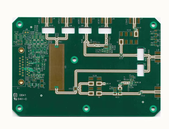
Comparing Rogers 4003C To Other High-Frequency PCB Materials
When it comes to high-frequency printed circuit board (PCB) materials, Rogers 4003C stands out as a popular choice among engineers and designers. This material is renowned for its excellent electrical performance and mechanical stability, making it a preferred option for a variety of applications, including RF and microwave circuits. However, to fully appreciate the advantages of Rogers 4003C, it is essential to compare it with other high-frequency PCB materials available in the market.
One of the primary competitors to Rogers 4003C is the FR-4 material, which is widely used in the PCB industry due to its cost-effectiveness and versatility.
However, FR-4 falls short in high-frequency applications because of its higher dielectric constant and loss tangent. These properties can lead to signal degradation and increased losses at higher frequencies, making FR-4 less suitable for applications requiring precise signal integrity. In contrast, Rogers 4003C offers a lower dielectric constant and loss tangent, ensuring minimal signal loss and superior performance in high-frequency environments.
Another material often compared to Rogers 4003C is the PTFE (Polytetrafluoroethylene)-based laminates, such as those offered by Taconic and Arlon.
PTFE materials are known for their excellent electrical properties, including low dielectric constant and loss tangent, which are comparable to those of Rogers 4003C. However, PTFE laminates can be more challenging to process due to their softer and more flexible nature. This can lead to difficulties in drilling, plating, and other manufacturing processes, potentially increasing production costs and time. Rogers 4003C, on the other hand, combines the electrical performance of PTFE with the mechanical robustness of traditional epoxy-based materials, offering a more balanced solution for high-frequency PCB applications.
In addition to PTFE, ceramic-filled laminates such as Rogers RO4350B are also considered high-performance alternatives.
These materials provide excellent thermal stability and low dielectric loss, making them suitable for high-power and high-frequency applications. However, ceramic-filled laminates can be more brittle and prone to cracking under mechanical stress, which can be a concern during the manufacturing and assembly processes. Rogers 4003C, with its unique blend of ceramic and hydrocarbon materials, offers a compromise between electrical performance and mechanical durability, making it a more versatile option for a wide range of applications.
Furthermore, the thermal management capabilities of Rogers 4003C are noteworthy.
While materials like FR-4 can suffer from thermal expansion and warping under high temperatures, Rogers 4003C maintains its dimensional stability, ensuring reliable performance even in demanding thermal environments. This characteristic is particularly important in applications such as power amplifiers and antennas, where thermal management is critical to maintaining signal integrity and overall system performance.
In conclusion, while there are several high-frequency PCB materials available, Rogers 4003C distinguishes itself through its combination of excellent electrical properties, mechanical stability, and ease of processing. Compared to FR-4, PTFE-based laminates, and ceramic-filled materials, Rogers 4003C offers a balanced solution that addresses the key challenges of high-frequency PCB design and manufacture. Its unique properties make it an ideal choice for a wide range of applications, ensuring reliable performance and cost-effective production. As the demand for high-frequency and high-performance PCBs continues to grow, Rogers 4003C remains a leading material that meets the evolving needs of the industry.
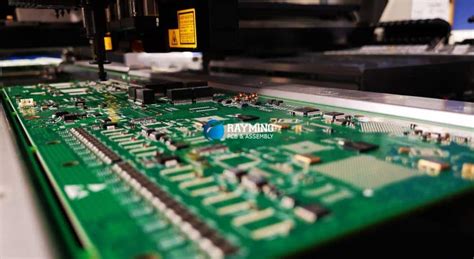
Design Considerations For PCBs Using Rogers 4003C Material
When designing printed circuit boards (PCBs) using Rogers 4003C material, several critical considerations must be taken into account to ensure optimal performance and reliability. Rogers 4003C is a high-frequency laminate known for its excellent electrical properties, making it a preferred choice for RF and microwave applications. However, its unique characteristics necessitate a thorough understanding of design principles to fully leverage its advantages.
To begin with, the dielectric constant (Dk) of Rogers 4003C is relatively stable over a wide frequency range, typically around 3.38.
This stability is crucial for maintaining signal integrity in high-frequency circuits. Designers must carefully calculate the impedance of transmission lines, as any deviation can lead to signal loss or reflection. Utilizing simulation tools to model the PCB layout can help in predicting and mitigating potential issues related to impedance mismatches.
Another important factor is the material’s low dissipation factor (Df), which is approximately 0.0027 at 10 GHz.
This low Df minimizes signal attenuation, making Rogers 4003C ideal for applications requiring minimal signal loss. However, designers should still be mindful of the layout to avoid unnecessary long trace lengths and sharp bends, which can introduce additional losses and degrade performance.
Thermal management is another critical aspect when working with Rogers 4003C.
Although it has a relatively low coefficient of thermal expansion (CTE), which enhances dimensional stability, it is essential to consider the thermal conductivity of the material. Proper heat dissipation techniques, such as the use of thermal vias and heat sinks, should be incorporated into the design to prevent overheating and ensure the longevity of the PCB.
The mechanical properties of Rogers 4003C also play a significant role in the design process.
The material’s rigidity and durability make it suitable for multilayer PCB constructions. However, designers must pay attention to the layer stack-up configuration to maintain the mechanical integrity of the board. Ensuring a balanced stack-up can prevent warping and bowing, which are critical for maintaining precise alignment in high-frequency circuits.
Moreover, the choice of surface finish is another consideration that can impact the performance of PCBs using Rogers 4003C.
Common finishes such as ENIG (Electroless Nickel Immersion Gold) or immersion silver are often preferred due to their excellent conductivity and reliability. The surface finish must be compatible with the soldering process to ensure strong and reliable solder joints, which are vital for the overall performance and durability of the PCB.
Additionally, the selection of appropriate components and their placement on the PCB is crucial.
High-frequency components should be placed as close to the signal source as possible to minimize signal path lengths and reduce potential interference. Ground planes and shielding techniques can also be employed to further enhance signal integrity and reduce electromagnetic interference (EMI).
In conclusion, designing PCBs with Rogers 4003C material requires a comprehensive understanding of its electrical, thermal, and mechanical properties. By carefully considering factors such as impedance control, thermal management, mechanical stability, surface finish, and component placement, designers can fully exploit the advantages of Rogers 4003C to create high-performance, reliable PCBs for RF and microwave applications. Through meticulous planning and attention to detail, the unique benefits of Rogers 4003C can be harnessed to meet the demanding requirements of modern electronic systems.

