Rf pcb transmission line
Design Techniques For RF PCB Transmission Lines
Designing RF PCB transmission lines requires a meticulous approach to ensure signal integrity and minimize losses. The first step in this process involves selecting the appropriate substrate material, as the dielectric constant and loss tangent of the substrate significantly impact the performance of the transmission line.
Common materials include FR4, Rogers, and Teflon, each offering distinct advantages and trade-offs in terms of cost, performance, and manufacturability. Once the substrate is chosen, the next critical aspect is determining the transmission line geometry, which can be either microstrip, stripline, or coplanar waveguide, depending on the specific application requirements.
Microstrip lines are widely used due to their simplicity and ease of fabrication.
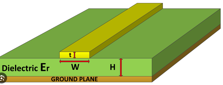
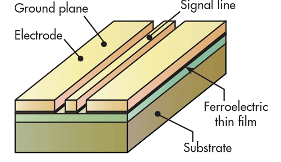
They consist of a conductive trace on one side of the substrate with a ground plane on the opposite side. However, microstrip lines are susceptible to radiation losses and interference from nearby components. To mitigate these issues, designers often employ ground vias and shielding techniques. In contrast, stripline configurations, which sandwich the conductive trace between two ground planes, offer superior isolation and reduced radiation losses but are more complex to manufacture. Coplanar waveguides, featuring a conductive trace flanked by ground planes on the same layer, provide a balance between performance and ease of fabrication, making them suitable for high-frequency applications.
Impedance matching is another crucial consideration in RF PCB transmission line design.
Mismatched impedance can lead to signal reflections, resulting in power loss and signal distortion. To achieve proper impedance matching, designers must carefully calculate the width and spacing of the transmission lines based on the substrate’s dielectric constant and the desired characteristic impedance, typically 50 ohms. Advanced simulation tools, such as electromagnetic field solvers, are often employed to model and optimize the transmission line geometry, ensuring accurate impedance control.
In addition to impedance matching, minimizing signal loss is essential for maintaining signal integrity in RF PCB transmission lines.
Losses can arise from various sources, including conductor losses, dielectric losses, and radiation losses. Conductor losses, caused by the resistance of the conductive trace, can be minimized by using wider traces or lower-resistance materials like copper. Dielectric losses, resulting from the substrate material’s inherent properties, can be reduced by selecting low-loss substrates. Radiation losses, which occur when the transmission line emits electromagnetic energy, can be mitigated through proper shielding and layout techniques.
Another important aspect of RF PCB transmission line design is managing crosstalk and electromagnetic interference (EMI).
Crosstalk occurs when signals from adjacent transmission lines couple into each other, leading to signal degradation. To minimize crosstalk, designers should maintain adequate spacing between transmission lines and use ground planes or vias to isolate them. EMI, on the other hand, can be addressed by implementing proper grounding and shielding practices, as well as using differential signaling techniques to reduce susceptibility to external noise.
Thermal management is also a key consideration in RF PCB transmission line design, as excessive heat can degrade performance and reliability. Effective thermal management strategies include using thermal vias to dissipate heat, selecting substrates with good thermal conductivity, and optimizing the layout to distribute heat evenly.
In conclusion, designing RF PCB transmission lines involves a comprehensive understanding of various factors, including substrate selection, transmission line geometry, impedance matching, signal loss minimization, crosstalk and EMI management, and thermal management. By carefully considering these aspects and employing advanced simulation tools, designers can create high-performance RF PCB transmission lines that meet the stringent requirements of modern communication systems.
Material Selection For Optimal RF PCB Performance
When designing RF PCBs, the selection of materials is paramount to achieving optimal performance. The choice of substrate material directly influences the electrical properties, thermal management, and overall reliability of the RF transmission lines. Consequently, understanding the characteristics of various materials and their impact on RF performance is essential for engineers and designers.
To begin with, the dielectric constant (Dk) of the substrate material plays a crucial role in determining the signal propagation speed and impedance of the transmission lines.
Materials with a low dielectric constant, such as PTFE (Polytetrafluoroethylene), are often preferred for high-frequency applications because they minimize signal loss and dispersion. PTFE, commonly known by the brand name Teflon, offers excellent electrical properties, including a low Dk and low dissipation factor, making it suitable for RF and microwave circuits. However, PTFE’s mechanical properties, such as its tendency to deform under pressure, necessitate careful handling and processing.
In addition to the dielectric constant, the loss tangent (tan δ) is another critical parameter.
The loss tangent measures the inherent energy loss within the material as the signal propagates through it. Materials with a low loss tangent, such as Rogers RO3000 series laminates, are highly desirable for RF applications because they ensure minimal signal attenuation. These laminates are engineered to provide a balance between low dielectric loss and mechanical stability, making them a popular choice for high-frequency circuits.
Thermal management is another vital consideration in RF PCB material selection.
High-frequency signals generate significant heat, which can affect the performance and longevity of the PCB. Materials with high thermal conductivity, such as ceramic-filled PTFE composites, help dissipate heat more effectively, thereby maintaining the integrity of the transmission lines. Additionally, these materials exhibit low thermal expansion coefficients, which is crucial for maintaining dimensional stability under varying thermal conditions.
Moreover, the surface roughness of the copper cladding on the substrate material can impact the performance of RF transmission lines.
A smoother copper surface reduces conductor losses and improves signal integrity. Advanced materials, such as low-profile copper foils, are designed to minimize surface roughness and enhance high-frequency performance. These foils are often used in conjunction with high-performance substrates to achieve the desired electrical characteristics.
Furthermore, environmental factors, such as moisture absorption, can degrade the performance of RF PCBs.
Materials with low moisture absorption rates, such as hydrocarbon ceramic laminates, are preferred for applications where environmental stability is critical. These laminates offer a combination of low dielectric constant, low loss tangent, and excellent moisture resistance, making them suitable for a wide range of RF applications.
In conclusion, the selection of materials for RF PCBs is a multifaceted process that requires careful consideration of various electrical, thermal, and mechanical properties. By choosing materials with low dielectric constants, low loss tangents, high thermal conductivity, smooth copper surfaces, and low moisture absorption rates, designers can optimize the performance of RF transmission lines. As technology continues to advance, the development of new materials and the refinement of existing ones will play a crucial role in meeting the ever-increasing demands of high-frequency applications.
Common Challenges In RF PCB Transmission Line Design
Designing RF PCB transmission lines presents a unique set of challenges that require careful consideration and meticulous planning. One of the primary difficulties lies in managing signal integrity, which is crucial for maintaining the performance of high-frequency circuits. Signal integrity issues often arise from impedance mismatches, which can cause signal reflections and degrade the overall performance of the transmission line.
To mitigate this, designers must ensure that the characteristic impedance of the transmission line is consistent with the source and load impedances.
This often involves precise control over the PCB’s geometry, including the width of the traces and the spacing between them, as well as the dielectric properties of the substrate material.
Another significant challenge is minimizing signal loss, which can be exacerbated by the skin effect and dielectric losses at high frequencies.
The skin effect causes the current to concentrate near the surface of the conductor, increasing the effective resistance and, consequently, the signal loss. To address this, designers may opt for materials with lower resistivity or employ techniques such as plating the traces with a thin layer of a highly conductive material like gold or silver. Additionally, selecting a substrate with low dielectric loss tangent can help reduce dielectric losses, thereby preserving signal strength over longer distances.
Crosstalk is another critical issue that can compromise the performance of RF PCB transmission lines.
Crosstalk occurs when a signal transmitted on one line induces an unwanted signal on an adjacent line, leading to interference and potential data corruption. To minimize crosstalk, designers can increase the spacing between adjacent transmission lines or implement shielding techniques, such as using ground planes or guard traces. Furthermore, maintaining a consistent ground reference and employing differential signaling can also help reduce the impact of crosstalk.
Thermal management is yet another challenge in RF PCB transmission line design.
High-frequency signals can generate significant amounts of heat, which, if not properly managed, can lead to thermal expansion and mechanical stress on the PCB. This can result in changes to the transmission line’s impedance and, ultimately, signal degradation. Effective thermal management strategies include using materials with high thermal conductivity, incorporating thermal vias to dissipate heat, and designing the PCB layout to optimize heat distribution.
Moreover, electromagnetic interference (EMI) poses a substantial challenge in RF PCB transmission line design.
EMI can originate from various sources, including other electronic components, power supplies, and external devices. To mitigate EMI, designers can employ shielding techniques, such as enclosing the transmission lines in a grounded metal enclosure or using ferrite beads to suppress high-frequency noise. Additionally, careful layout practices, such as maintaining short and direct signal paths and avoiding sharp bends in the transmission lines, can help reduce EMI susceptibility.
Finally, manufacturability is a crucial consideration in RF PCB transmission line design.
The intricate geometries and tight tolerances required for high-frequency performance can complicate the manufacturing process, leading to increased costs and potential yield issues. Collaborating closely with PCB manufacturers during the design phase can help ensure that the design is both manufacturable and cost-effective. This collaboration can also facilitate the identification and resolution of potential issues early in the design process, thereby reducing the risk of costly rework or redesigns.
In conclusion, designing RF PCB transmission lines involves addressing a myriad of challenges, including signal integrity, signal loss, crosstalk, thermal management, EMI, and manufacturability. By employing careful design practices and leveraging advanced materials and techniques, designers can overcome these challenges and achieve high-performance RF transmission lines that meet the stringent requirements of modern electronic systems.
Advanced Simulation Tools For RF PCB Transmission Lines
Advanced simulation tools have become indispensable in the design and optimization of RF PCB transmission lines. These tools offer engineers the ability to model complex electromagnetic interactions, predict performance, and identify potential issues before physical prototypes are built. As the demand for higher frequencies and greater bandwidths continues to grow, the precision and capabilities of these simulation tools are more critical than ever.
One of the primary advantages of advanced simulation tools is their ability to accurately model the behavior of transmission lines under various conditions.
By using sophisticated algorithms and computational techniques, these tools can simulate the effects of different materials, geometries, and environmental factors on signal integrity. This level of detail is essential for ensuring that the transmission lines will perform as expected in real-world applications. Moreover, these simulations can help identify potential sources of signal degradation, such as crosstalk, reflection, and attenuation, allowing engineers to make informed design choices to mitigate these issues.
In addition to modeling the physical characteristics of transmission lines, advanced simulation tools also enable the analysis of electromagnetic compatibility (EMC) and electromagnetic interference (EMI).
These factors are particularly important in RF applications, where even minor disruptions can significantly impact performance. By simulating the electromagnetic environment, engineers can assess the potential for interference and take steps to minimize its effects. This might involve adjusting the layout of the PCB, selecting different materials, or incorporating shielding techniques.
Furthermore, advanced simulation tools facilitate the optimization of transmission line designs.
Through iterative simulations, engineers can explore a wide range of design parameters and configurations to identify the optimal solution. This process not only improves the performance of the transmission lines but also helps to reduce development time and costs. By identifying the best design early in the development process, engineers can avoid costly and time-consuming revisions later on.
Another significant benefit of these tools is their ability to integrate with other design and analysis software.
This integration allows for a more comprehensive approach to PCB design, where the transmission lines can be evaluated in the context of the entire system. For example, thermal analysis tools can be used in conjunction with electromagnetic simulations to assess the impact of temperature on transmission line performance. Similarly, mechanical analysis tools can help evaluate the effects of physical stress and strain on the PCB. This holistic approach ensures that all aspects of the design are considered, leading to more robust and reliable products.
Moreover, the use of advanced simulation tools is not limited to the design phase.
These tools can also be employed during the testing and validation stages to compare simulated results with actual measurements. This comparison helps to verify the accuracy of the simulations and identify any discrepancies that may need to be addressed. By continuously refining the simulation models based on real-world data, engineers can improve the accuracy and reliability of their predictions.
In conclusion, advanced simulation tools play a crucial role in the design and optimization of RF PCB transmission lines. By providing detailed insights into the behavior of transmission lines under various conditions, these tools enable engineers to make informed design choices, optimize performance, and ensure electromagnetic compatibility. The integration of these tools with other design and analysis software further enhances their utility, leading to more robust and reliable products. As the demand for higher frequencies and greater bandwidths continues to grow, the importance of advanced simulation tools in RF PCB design will only increase.

