Pcb s-parameter
UnderstandingPCB S-Parameters in PCB Design
In the realm of printed circuit board (PCB) design, understanding S-parameters is crucial for ensuring optimal performance, particularly in high-frequency applications. S-parameters, or scattering parameters, are a set of measurements that describe how electrical signals behave in a network, such as a PCB, when subjected to various frequencies. These parameters are essential for characterizing the electrical behavior of components and interconnections, thereby enabling engineers to predict and mitigate potential issues related to signal integrity, reflection, and transmission losses.
To begin with, S-parameters are typically represented in a matrix form, where each element of the matrix corresponds to a specific interaction between ports in the network.
For instance, in a two-port network, the S-parameter matrix consists of four elements: S11, S21, S12, and S22. Each of these elements provides valuable information about the network’s behavior. S11 and S22 represent the reflection coefficients at port 1 and port 2, respectively, indicating how much of the incoming signal is reflected back due to impedance mismatches. On the other hand, S21 and S12 represent the transmission coefficients, which describe how much of the signal is transmitted from one port to the other.
Moreover, the significance of S-parameters in PCB design cannot be overstated.
High-frequency signals are particularly susceptible to various forms of degradation, such as attenuation, crosstalk, and electromagnetic interference. By analyzing S-parameters, engineers can identify and address these issues early in the design process. For example, a high S11 value might indicate a poor impedance match, leading to significant signal reflection and potential data loss. By adjusting the trace width, spacing, or dielectric material, designers can optimize the impedance and minimize reflections, thereby enhancing signal integrity.
Furthermore, S-parameters are invaluable for the design and optimization of high-speed interconnects, such as differential pairs and transmission lines.
Differential pairs, commonly used in high-speed data communication, require precise impedance matching to ensure minimal signal degradation. By examining the S-parameters, designers can fine-tune the physical layout and material properties to achieve the desired performance. Similarly, for transmission lines, S-parameters help in understanding the propagation characteristics and identifying potential sources of loss or distortion.
In addition to their role in design, S-parameters are also essential for validating and verifying PCB performance.
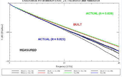
Once a PCB is fabricated, engineers can measure its S-parameters using vector network analyzers (VNAs) to ensure that the actual performance aligns with the design specifications. Any discrepancies can then be traced back to potential manufacturing defects or design flaws, allowing for corrective actions to be taken.
Transitioning to the practical aspects, the use of simulation tools has become increasingly prevalent in modern PCB design workflows.
Software such as SPICE, HFSS, and ADS enable engineers to simulate the S-parameters of their designs before physical prototyping. This not only accelerates the design process but also reduces costs associated with iterative prototyping and testing. By leveraging these tools, designers can explore various design scenarios, optimize performance, and ensure compliance with industry standards.
In conclusion, understanding and utilizing S-parameters is fundamental for successful PCB design, particularly in high-frequency applications. These parameters provide critical insights into the electrical behavior of components and interconnections, enabling engineers to optimize signal integrity, minimize losses, and ensure reliable performance. Through careful analysis and simulation, designers can address potential issues early in the design process, ultimately leading to more robust and efficient PCB designs.

Importance of S-Parameters for High-Frequency PCB Applications
In the realm of high-frequency printed circuit board (PCB) applications, the significance of S-parameters, or scattering parameters, cannot be overstated. These parameters are essential for characterizing the electrical behavior of linear RF and microwave networks, providing critical insights into how signals propagate through a PCB. As the demand for high-speed data transmission and advanced communication systems continues to grow, understanding and utilizing S-parameters becomes increasingly vital for engineers and designers.
S-parameters offer a comprehensive way to describe the performance of high-frequency circuits.
Unlike traditional time-domain analysis, which can be cumbersome and less intuitive at high frequencies, S-parameters operate in the frequency domain, making them particularly suited for RF and microwave applications. They provide a clear picture of how much of an input signal is reflected back, how much is transmitted through, and how much is coupled to other ports. This information is crucial for ensuring signal integrity, minimizing losses, and optimizing the overall performance of the PCB.
One of the primary advantages of using S-parameters is their ability to simplify complex network analysis.
By representing the network in terms of reflection and transmission coefficients, engineers can easily cascade multiple network elements and predict the overall behavior of the system. This modular approach is especially beneficial in high-frequency designs, where components such as filters, amplifiers, and transmission lines must work seamlessly together. Moreover, S-parameters are inherently compatible with simulation tools, allowing for accurate modeling and optimization before physical prototypes are built.
Transitioning from theoretical benefits to practical applications, S-parameters play a crucial role in impedance matching.
In high-frequency circuits, impedance mismatches can lead to significant signal reflections, resulting in power loss and potential signal distortion. By analyzing the S-parameters, designers can identify mismatches and make necessary adjustments to ensure maximum power transfer and minimal reflection. This is particularly important in applications such as wireless communication, radar systems, and high-speed digital interfaces, where signal integrity is paramount.
Furthermore, S-parameters are instrumental in characterizing the performance of PCB materials and interconnects.
As frequencies increase, the dielectric properties of the substrate and the quality of the interconnects become critical factors. S-parameter measurements can reveal losses due to dielectric absorption, conductor losses, and radiation, enabling designers to select appropriate materials and optimize the layout for high-frequency operation. This level of insight is essential for achieving the desired performance in applications such as 5G networks, satellite communications, and advanced sensor systems.
In addition to their role in design and optimization, S-parameters are also valuable for troubleshooting and quality assurance.
By comparing measured S-parameters with simulated or expected values, engineers can identify discrepancies that may indicate manufacturing defects, component failures, or design flaws. This diagnostic capability is crucial for maintaining the reliability and performance of high-frequency PCBs, especially in mission-critical applications where failure is not an option.
In conclusion, the importance of S-parameters for high-frequency PCB applications is multifaceted, encompassing design, optimization, material selection, and quality assurance. Their ability to provide detailed insights into the electrical behavior of RF and microwave networks makes them indispensable tools for engineers and designers. As technology continues to advance and the demand for high-speed, high-frequency applications grows, the role of S-parameters in ensuring signal integrity and overall system performance will only become more critical.

How to Measure and Analyze S-Parameters in PCBs
In the realm of high-frequency circuit design, the measurement and analysis of S-parameters (scattering parameters) in printed circuit boards (PCBs) are crucial for ensuring optimal performance. S-parameters provide a comprehensive understanding of how RF signals behave within a network, offering insights into reflection, transmission, and impedance characteristics. To measure and analyze these parameters effectively, a systematic approach is required, encompassing both theoretical knowledge and practical application.
To begin with, it is essential to understand what S-parameters represent.
In essence, S-parameters describe the electrical behavior of linear RF and microwave devices. They are particularly useful in characterizing how signals are transmitted and reflected through a network, which is critical for high-frequency PCB design. The parameters are typically represented in a matrix form, where each element corresponds to a specific interaction between ports in the network. For instance, S11 represents the reflection coefficient at port 1, while S21 denotes the forward transmission coefficient from port 1 to port 2.
The first step in measuring S-parameters involves the use of a Vector Network Analyzer (VNA).
This sophisticated instrument is designed to measure the complex transmission and reflection characteristics of RF components. Before initiating the measurement, it is imperative to calibrate the VNA to eliminate systematic errors and ensure accuracy. Calibration involves using known standards such as open, short, and load to establish a reference point. Once calibrated, the VNA can be connected to the PCB under test, typically through coaxial cables or specialized probes.
During the measurement process, the VNA sends a known signal through the PCB and measures the resulting transmitted and reflected signals.
These measurements are then used to calculate the S-parameters. It is important to perform these measurements over the frequency range of interest to capture the frequency-dependent behavior of the PCB. The resulting S-parameter data can be displayed in various formats, including Smith charts, magnitude and phase plots, and polar plots, each offering unique insights into the PCB’s performance.
Analyzing the measured S-parameters is the next critical step.
This analysis involves interpreting the data to understand the PCB’s behavior under different conditions. For instance, a high S11 value indicates significant reflection, suggesting impedance mismatches that could lead to signal integrity issues. Conversely, a low S21 value implies poor transmission, which could be due to losses or other impairments within the PCB. By examining these parameters, engineers can identify potential issues and make informed decisions to optimize the PCB design.
Moreover, advanced simulation tools can be employed to complement the measurement process.
These tools allow engineers to model the PCB and predict its S-parameters under various scenarios. By comparing simulated and measured data, discrepancies can be identified and addressed, leading to more accurate and reliable designs. Additionally, time-domain analysis techniques, such as Time Domain Reflectometry (TDR), can be used in conjunction with S-parameter measurements to provide a more comprehensive understanding of the PCB’s performance.
In conclusion, the measurement and analysis of S-parameters in PCBs are indispensable for high-frequency circuit design. By leveraging tools like VNAs and simulation software, engineers can gain valuable insights into the behavior of RF signals within a PCB. This knowledge enables the identification and mitigation of potential issues, ultimately leading to more efficient and reliable designs. Through meticulous measurement, thorough analysis, and iterative optimization, the performance of high-frequency PCBs can be significantly enhanced, ensuring they meet the stringent demands of modern electronic applications.

Common Mistakes to Avoid When Using S-Parameters in PCB Design
When utilizing S-parameters in PCB design, it is crucial to be aware of common mistakes that can compromise the integrity and performance of your circuit. One frequent error is neglecting the importance of proper calibration. Calibration is essential to ensure that the measurements taken are accurate and reflective of the actual performance of the PCB. Without proper calibration, the S-parameters obtained may be misleading, leading to incorrect design decisions and potential failures in the final product.
Another common mistake is the improper handling of connectors and cables.
The quality and condition of these components can significantly affect the accuracy of S-parameter measurements. Using worn-out or incompatible connectors and cables can introduce noise and signal degradation, which can distort the S-parameters. Therefore, it is imperative to use high-quality, well-maintained connectors and cables that are appropriate for the frequency range of your measurements.
Additionally, overlooking the impact of environmental factors can lead to erroneous S-parameter data.
Temperature, humidity, and electromagnetic interference can all influence the performance of a PCB and, consequently, the S-parameters. It is important to conduct measurements in a controlled environment to minimize these external influences. Furthermore, ensuring that the PCB is properly shielded from electromagnetic interference can help in obtaining more accurate S-parameter data.
Another pitfall to avoid is the incorrect interpretation of S-parameters.
S-parameters are complex numbers that represent both magnitude and phase information. Misinterpreting these parameters can lead to incorrect conclusions about the performance of the PCB. It is essential to have a thorough understanding of how to read and analyze S-parameters to make informed design decisions. This includes being aware of the significance of parameters such as return loss, insertion loss, and phase shift, and how they relate to the overall performance of the PCB.
Moreover, failing to consider the frequency range of interest can result in suboptimal design choices.
S-parameters are frequency-dependent, and their behavior can vary significantly across different frequency ranges. It is important to ensure that the S-parameters are measured and analyzed over the entire frequency range relevant to your application. Ignoring certain frequency ranges can lead to unexpected performance issues in the final product.
Another mistake to avoid is the improper de-embedding of test fixtures.
Test fixtures are often used to facilitate the measurement of S-parameters, but they can introduce their own parasitic effects. De-embedding is the process of removing these parasitic effects to obtain the true S-parameters of the PCB. Failing to properly de-embed the test fixtures can result in inaccurate S-parameter data, leading to flawed design decisions.
Lastly, it is important to avoid the assumption that S-parameters alone are sufficient for a comprehensive analysis of PCB performance.
While S-parameters provide valuable information about the linear behavior of the PCB, they do not capture non-linear effects such as harmonics and intermodulation distortion. It is important to complement S-parameter analysis with other types of measurements and simulations to obtain a complete understanding of the PCB’s performance.
In conclusion, avoiding these common mistakes when using S-parameters in PCB design can significantly enhance the accuracy and reliability of your measurements, leading to better design decisions and improved performance of the final product. By paying attention to calibration, handling of connectors and cables, environmental factors, interpretation of S-parameters, frequency range considerations, de-embedding of test fixtures, and complementing S-parameter analysis with other methods, you can ensure a more robust and effective PCB design process.

