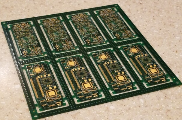
Metal core pcb soldering
Techniques For Soldering Metal Core PCBs
Soldering metal core printed circuit boards (MCPCBs) presents unique challenges and requires specialized techniques to ensure reliable and effective connections. Unlike traditional PCBs, which are typically made from materials like FR4, MCPCBs incorporate a metal core, usually aluminum or copper, to enhance thermal management. This core helps dissipate heat more efficiently, making MCPCBs ideal for high-power applications such as LED lighting, power supplies, and automotive electronics. However, the presence of a metal core necessitates careful consideration during the soldering process to avoid potential issues such as thermal stress, poor solder joints, and component damage.
One of the primary techniques for soldering MCPCBs involves the use of a preheating stage.
Preheating the board helps to reduce thermal shock and ensures a more uniform temperature distribution across the PCB. This step is crucial because the metal core can act as a heat sink, drawing heat away from the soldering area and making it difficult to achieve the necessary temperatures for proper soldering. By preheating the board, the thermal gradient between the soldering iron and the PCB is minimized, leading to more consistent and reliable solder joints.
In addition to preheating, selecting the appropriate soldering tools and materials is essential.
High-power soldering irons or reflow ovens with precise temperature control are recommended to handle the increased thermal demands of MCPCBs. The choice of solder paste or wire is also critical; lead-free solder with a higher melting point is often preferred due to its better thermal performance. Flux, which helps to clean and prepare the surfaces for soldering, should be chosen based on its compatibility with the materials used in the MCPCB and the specific components being soldered.
Another important technique is the use of thermal relief pads.
These pads are designed to isolate the soldering area from the metal core, reducing the amount of heat that is conducted away from the joint. Thermal relief pads typically consist of a small area of copper connected to the larger copper plane by narrow traces. This design helps to concentrate the heat in the soldering area, making it easier to achieve a good solder joint without overheating the surrounding components or the metal core itself.
Furthermore, the soldering process for MCPCBs often involves multiple stages, including initial soldering, inspection, and rework if necessary.
During the initial soldering stage, it is important to apply the solder evenly and avoid excessive heat, which can damage the components or the PCB. After soldering, thorough inspection using tools such as X-ray imaging or automated optical inspection (AOI) systems can help identify any defects or issues that need to be addressed. If rework is required, it should be performed carefully to avoid further stressing the PCB and components.
In conclusion, soldering metal core PCBs requires a combination of specialized techniques and careful attention to detail.
Preheating the board, selecting the appropriate tools and materials, using thermal relief pads, and conducting thorough inspections are all critical steps in ensuring reliable and effective solder joints. By understanding and implementing these techniques, manufacturers can take full advantage of the thermal management benefits offered by MCPCBs while maintaining the integrity and performance of their electronic assemblies.
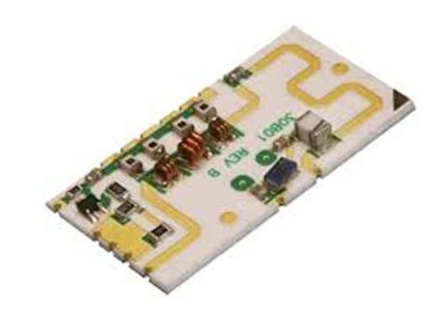
Common Mistakes In Metal Core PCB Soldering
Metal core printed circuit boards (PCBs) are increasingly popular in applications requiring efficient heat dissipation, such as LED lighting and power electronics. However, soldering these PCBs presents unique challenges that can lead to common mistakes if not properly addressed. Understanding these pitfalls is crucial for ensuring the reliability and performance of the final product.
One prevalent mistake in metal core PCB soldering is inadequate thermal management.
Metal core PCBs are designed to dissipate heat effectively, but this same property can make soldering more difficult. The metal core can act as a heat sink, drawing heat away from the soldering area and making it challenging to achieve the necessary temperatures for proper solder flow. Consequently, insufficient heat can result in cold solder joints, which are weak and prone to failure. To mitigate this, it is essential to use soldering equipment capable of delivering consistent and adequate heat, such as a soldering iron with temperature control or a reflow oven with precise thermal profiling.
Another common error is the improper selection of soldering materials.
The choice of solder paste and flux is critical in metal core PCB soldering. Using a solder paste with a low melting point can help in achieving good solder joints without overheating the components. Additionally, the flux should be compatible with the metal core material to ensure proper wetting and adhesion. Failure to select appropriate materials can lead to poor solder joint quality and reduced reliability of the PCB.
Furthermore, improper handling and preparation of the metal core PCB can lead to soldering issues.
Contaminants such as oils, dust, and oxidation on the PCB surface can prevent proper solder adhesion. Therefore, it is imperative to clean the PCB thoroughly before soldering. This can be done using isopropyl alcohol or specialized PCB cleaning solutions. Additionally, ensuring that the PCB is free from mechanical damage, such as scratches or dents, is crucial as these imperfections can affect the soldering process and the overall integrity of the PCB.
Moreover, incorrect component placement is another frequent mistake.
Metal core PCBs often have a higher density of components due to their use in high-power applications. Misalignment or improper placement of components can lead to solder bridges, short circuits, and other defects. Utilizing automated pick-and-place machines can help in achieving precise component placement. However, manual inspection and correction are still necessary to ensure that all components are correctly positioned before soldering.
In addition to these issues, inadequate inspection and testing post-soldering can result in undetected defects.
Visual inspection alone may not be sufficient to identify all potential problems. Implementing additional testing methods, such as X-ray inspection and electrical testing, can help in detecting hidden defects like voids, insufficient solder, or internal short circuits. Ensuring thorough inspection and testing is vital for maintaining the quality and reliability of metal core PCBs.
Lastly, neglecting to consider the thermal expansion properties of the metal core and the components can lead to long-term reliability issues.
The difference in thermal expansion coefficients between the metal core and the components can cause stress on the solder joints during thermal cycling. Designing the PCB layout to accommodate these differences and using flexible solder joints can help in mitigating this issue.
In conclusion, metal core PCB soldering requires careful attention to thermal management, material selection, handling and preparation, component placement, and thorough inspection and testing. By addressing these common mistakes, manufacturers can enhance the reliability and performance of their metal core PCBs, ensuring they meet the demanding requirements of high-power applications.
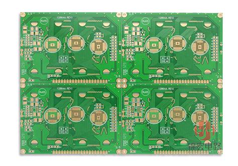
Tools And Equipment For Metal Core PCB Soldering
Metal core printed circuit boards (PCBs) are increasingly popular in applications requiring efficient heat dissipation, such as LED lighting and power electronics. Soldering these specialized PCBs necessitates a distinct set of tools and equipment to ensure optimal performance and reliability. Understanding the essential tools and equipment for metal core PCB soldering is crucial for achieving high-quality results.
To begin with, a high-quality soldering iron is indispensable.
Unlike standard PCBs, metal core PCBs often require higher temperatures due to their enhanced thermal conductivity. Therefore, a soldering iron with adjustable temperature control is recommended. This allows the user to precisely set the temperature, ensuring that the solder melts properly without damaging the components or the board itself. Additionally, a soldering iron with a fine tip is beneficial for working on the intricate and densely packed areas of the PCB.
Equally important is the choice of solder.
Lead-free solder is commonly used due to environmental and health considerations. However, it has a higher melting point compared to traditional leaded solder. Therefore, selecting a solder with an appropriate flux core is essential to facilitate the soldering process. Flux helps to clean the surfaces being soldered, promoting better adhesion and reducing the likelihood of cold joints. For metal core PCBs, a rosin-based flux is often preferred due to its effectiveness in removing oxides and ensuring a strong bond.
In addition to the soldering iron and solder, a reliable soldering station is vital.
A soldering station typically includes a stand for the soldering iron, a sponge or brass wool for cleaning the tip, and a temperature control unit. The stand provides a safe place to rest the hot soldering iron, while the cleaning materials help maintain the tip’s condition, ensuring consistent performance. The temperature control unit allows for precise adjustments, which is particularly important when working with metal core PCBs to avoid overheating and potential damage.
Furthermore, a hot air rework station can be extremely useful, especially for surface-mount components.
This tool uses a stream of hot air to heat the solder joints, allowing for the removal and replacement of components without direct contact. This is particularly advantageous for metal core PCBs, where the risk of thermal damage is higher. The hot air rework station should have adjustable temperature and airflow settings to accommodate different components and board configurations.
Another essential tool is a desoldering pump or solder wick.
These tools are used to remove excess solder or to correct mistakes. A desoldering pump creates a vacuum to suck up molten solder, while solder wick, made of braided copper, absorbs the solder when heated. Both tools are invaluable for reworking and repairing metal core PCBs, ensuring that the solder joints are clean and free of excess material.
Moreover, a magnifying lamp or microscope is highly recommended for inspecting solder joints.
Metal core PCBs often feature small and densely packed components, making it challenging to visually inspect the quality of the solder joints. A magnifying lamp or microscope provides the necessary magnification to identify any issues, such as cold joints, bridges, or insufficient solder coverage.
Lastly, personal protective equipment (PPE) should not be overlooked.
Soldering involves exposure to high temperatures and potentially harmful fumes. Therefore, safety glasses, heat-resistant gloves, and a fume extractor are essential to protect the user from burns and inhalation of toxic fumes.
In conclusion, soldering metal core PCBs requires a specialized set of tools and equipment to ensure high-quality and reliable results. A high-quality soldering iron with adjustable temperature control, appropriate solder and flux, a reliable soldering station, a hot air rework station, desoldering tools, magnification aids, and personal protective equipment are all crucial components. By investing in these tools and equipment, one can achieve precise and effective soldering, ensuring the optimal performance of metal core PCBs in their respective applications.
Benefits Of Using Metal Core PCBs In High-Temperature Applications
Metal core printed circuit boards (PCBs) have become increasingly popular in high-temperature applications due to their unique properties and numerous benefits. These PCBs are designed with a metal core, typically aluminum or copper, which provides superior thermal conductivity compared to traditional fiberglass-based PCBs. This enhanced thermal management is crucial in high-temperature environments, where excessive heat can lead to component failure and reduced performance.
One of the primary benefits of using metal core PCBs in high-temperature applications is their ability to efficiently dissipate heat.
The metal core acts as a heat sink, drawing heat away from critical components and distributing it evenly across the board. This prevents localized hotspots, which can cause thermal stress and damage to sensitive electronic components. Consequently, devices that utilize metal core PCBs tend to have a longer lifespan and greater reliability, making them ideal for demanding applications such as LED lighting, automotive electronics, and power supplies.
In addition to improved thermal management, metal core PCBs offer enhanced mechanical stability.
The metal core provides a robust foundation that resists warping and deformation, even under extreme temperature fluctuations. This stability is particularly important in applications where the PCB is subjected to harsh environmental conditions, such as in aerospace and industrial machinery. By maintaining their structural integrity, metal core PCBs ensure consistent performance and reduce the risk of mechanical failure.
Furthermore, metal core PCBs exhibit excellent electrical insulation properties.
The insulating layer between the metal core and the conductive copper traces ensures that electrical signals are transmitted without interference. This is especially beneficial in high-power applications, where maintaining signal integrity is critical. The combination of thermal and electrical performance makes metal core PCBs a versatile solution for a wide range of high-temperature applications.
Another advantage of metal core PCBs is their compatibility with surface mount technology (SMT).
SMT is a widely used method for assembling electronic components onto PCBs, and metal core PCBs can easily accommodate this technique. The metal core’s thermal conductivity aids in the soldering process, allowing for efficient heat transfer during reflow soldering. This results in strong, reliable solder joints that can withstand the rigors of high-temperature operation. Additionally, the metal core’s stability ensures that components remain securely attached, even in challenging environments.
Moreover, metal core PCBs contribute to overall system efficiency by reducing the need for additional cooling mechanisms.
Traditional PCBs often require heat sinks, fans, or other cooling solutions to manage heat dissipation. In contrast, the inherent thermal properties of metal core PCBs minimize the need for such auxiliary components, leading to more compact and lightweight designs. This not only simplifies the manufacturing process but also reduces costs and enhances the overall efficiency of the electronic system.
In conclusion, the benefits of using metal core PCBs in high-temperature applications are manifold. Their superior thermal management, mechanical stability, electrical insulation, and compatibility with surface mount technology make them an ideal choice for a variety of demanding environments. By effectively dissipating heat and maintaining structural integrity, metal core PCBs ensure reliable performance and longevity of electronic devices. As technology continues to advance and the demand for high-temperature applications grows, the adoption of metal core PCBs is likely to increase, further solidifying their importance in the electronics industry.


