Unveiling the ingenious grounding in electronic design: Why is the PCB ground connected to the metal case with a resistor and capacitor?
The grounding problem of electronic products is a common topic. This article only talks about a small part of it, mainly the grounding problem of the metal case and the circuit board. We often see that in some system designs, a high-voltage capacitor C1 (1~100nF/2KV) is usually connected in parallel with a large resistor R1 (1M) between the PCB board ground (GND) and the metal case (EGND). So why is it designed like this?
Figure 1: Schematic diagram
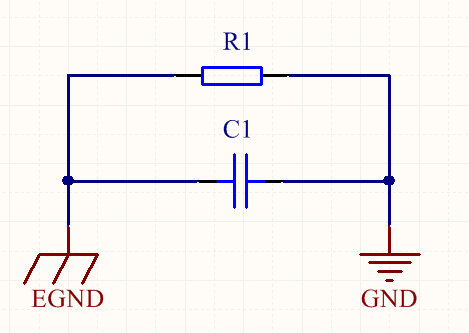
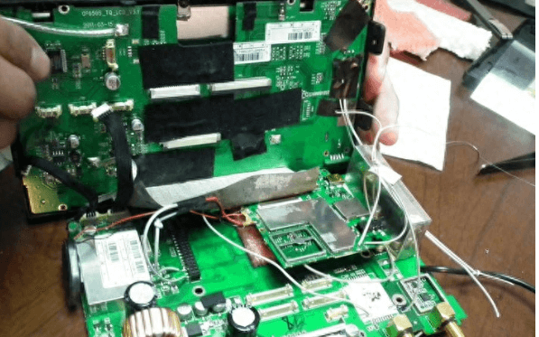
Figure 2: Actual PCB
The role of the capacitor
From the perspective of EMS (electromagnetic interference immunity), this capacitor is designed to reduce the impact of possible high-frequency interference signals with the ground potential as a reference on the circuit on the basis of ensuring that PE is connected to the ground, so as to achieve the purpose of suppressing the instantaneous common-mode voltage difference between the circuit and the interference source.
In fact, it is ideal to connect GND directly to PE, but direct connection may cause operational difficulties or safety hazards.
For example, the GND generated after the rectifier bridge cannot be directly connected to PE, so a path is designed that prevents low-frequency signals from passing through but allows high-frequency signals to pass through. From the perspective of EMI (electromagnetic interference), if there is a metal shell connected to PE, the existence of this high-frequency channel also helps prevent high-frequency signals from radiating to the external environment.
Capacitors pass AC and block DC.
Assuming that the chassis is well connected to the ground, from the perspective of electromagnetic immunity, the capacitor can suppress the dynamic common-mode voltage between the high-frequency interference source and the circuit; from the perspective of EMI, the capacitor forms a high-frequency path, and the high-frequency interference generated inside the circuit board will flow into the chassis and into the ground through the capacitor, avoiding antenna radiation formed by high-frequency interference.
In another case, assuming that the chassis is not reliably connected to the ground (such as no ground wire, the ground rod environment is dry), the shell potential may be unstable or have static electricity. If the circuit board is directly connected to the shell, it will damage the circuit board chip. Adding capacitors can isolate low-frequency high voltage, static electricity, etc. to protect the circuit board. This parallel capacitor should use a Y capacitor or a high-voltage film capacitor with a capacitance between 1nF and 100nF.
The role of the resistor
This resistor can effectively prevent ESD (electrostatic discharge) from damaging the circuit board. If only a capacitor is used to connect the circuit board ground to the shell ground, the circuit board will form a floating ground system. When conducting ESD testing or using it in a complex electromagnetic field environment, the charge injected into the circuit board is difficult to be effectively released, and will accumulate; when it accumulates to a certain extent, it exceeds the voltage value that the weakest point of the insulation between the circuit board and the shell can withstand, and it will cause a discharge phenomenon – in a very short time, tens to hundreds of amperes of current can be generated on the circuit board, which may cause the circuit to stop running due to electromagnetic pulses, or damage the connected components near the discharge site.
If this impedance is added, the charge can be gradually released and the high voltage can be eliminated. According to the ESD test standard of IEC61000, each discharge must complete the release of 2 kilovolts within 10 seconds, so it is generally recommended to use a resistor of 1 megohm to 2 megohm. If the shell carries high-voltage static electricity, this high-impedance component can also effectively reduce the current, thereby preventing damage to the circuit chip.
Issues that need attention
· If the device casing is well grounded, then the PCB should also be well grounded at a single point with the casing. At this time, the power frequency interference will be eliminated through the casing grounding, and will not interfere with the PCB;
· If there may be safety issues in the use of the device, the device casing must be well grounded;
· In order to achieve better results, it is recommended that the device casing is well grounded as much as possible, and the PCB is well grounded at a single point with the casing; of course, if the casing is not well grounded, it is better to float the PCB, that is, not connect it to the casing, because if the PCB is isolated from the earth (the so-called floating ground), the power frequency interference loop impedance is extremely large, but it will not cause any interference to the PCB;
· When multiple devices need to be connected to each other, it should be ensured that each device casing is well grounded at a single point with the earth, and the internal PCB of each device should also be grounded at a single point with its casing;
· However, if the device casing cannot be well grounded when multiple devices are connected to each other, it is more appropriate to turn it into a floating state, and the internal PCB does not need to be grounded with the casing;
· The chassis ground may not be an ideal grounding choice, for example, if the relevant safety regulations are not followed in the distribution network and there is no ground wire; or the soil around the grounding rod is too dry, and the grounding bolt is rusted or loose;
· There is electromagnetic interference in the environment, and there are high-power transformers, high-power motors, electromagnetic furnaces, high-voltage grid harmonics, etc. in the working environment;
· High-frequency noise will be generated inside the PCB, such as high-frequency switching tubes, diodes, energy storage inductors, high-frequency transformers, etc. These interference factors will cause the potential fluctuations of the signal ground of the PCB and the chassis (containing both high-frequency and low-frequency components), or there will be static electricity between the two, so good and reliable grounding treatment for them is necessary and is also required by product safety regulations.