How to Test for Shorts on PCBs
Every engineer has a “worst case scenario” story that they’ve survived. During the worst week of my career, we received a shipment of expired PCBs. These hardware had been installed in customer computers a month prior. We were a bit mortified.
Needless to say, these new boards were shipped in a bit of a rush. You could smell the ozone emanating from the boards once we powered them up for testing. One of the most expensive components heated up so hot that it burned a pair of guys who were doing the “touch test.” We figured, we didn’t have time to get a batch of test boards and just ordered fully populated PCBs.
Leaving aside the obvious frustration, sucking on a burned finger while explaining a major hardware failure to your boss is one of the worst meetings you can have. The best thing you can do is come up with a plan. If you’re ever in this situation, here’s how to become a master short finder on PCBs.
How to Check for Shorts in PCBs
There are some important steps in this article that can be used to locate shorts in your PCB design:
Step 1: How to Find Shorts in PCBs
Step 2: How to Test Circuits on Electronic Boards for Shorts
Step 3: How to Find Faulty Components on PCBs
Step 4: How to Destructively Test PCBs
Step 1: How to Find Shorts in PCBs
Visual Inspection
Assuming you are past the breadboard design stage and do not have a built-in circuit breaker, the first step to locating shorts on your PCB is to look closely at the entire surface of the PCB.
If you have one available, use a magnifying glass or low-power microscope during your board inspection. Start at the power supply and look forward, between pads or at solder joints. Watch for any solder or solder joint cracks.
Check all of your vias. If you have specified unplanned vias, make sure that is the case on the board. Poorly plated vias can create shorts between layers, leaving you with everything tied to GND, VCC, or both.
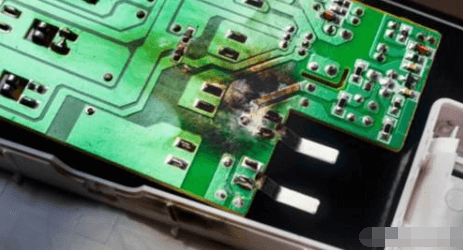
If the short is really bad, you will see burnt spots on the PCB when the component reaches critical temperatures.
They can be fairly small but will be noticeably discolored brown instead of the normal green solder mask. If you have multiple boards, a burned PCB can help you narrow down the exact location without having to power another board to be sacrificed in the search. Unfortunately, our board itself wasn’t burnt, just unlucky fingers checking the board to see if it was overheating.
Some shorts will be internal to the board and won’t create a burn spot. This also means they won’t be very noticeable from the surface layers. Here you’ll need some other method to detect shorts in your PCB.
Infrared Imaging
If you’re not at a startup that’s just over budget for hardware, you might be lucky enough to have an infrared camera. Using an infrared camera can help you find areas that are generating a lot of heat. If you don’t see hot spots away from your activated component, then you probably have a PCB short, even if the short is between internal layers.
A short will usually be higher resistance than a normal trace or solder joint because it has not been optimized away from the design (unless you really like ignoring rule checks). This resistance, along with the naturally high current flow due to the direct connection between power and ground, means that the conductors in a PCB short will heat up. From the lowest current. Ideally, you’ll see the short before it does more damage.
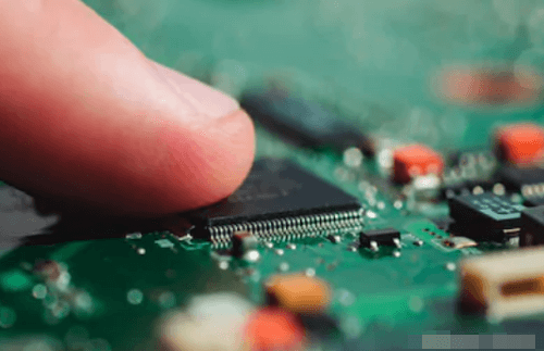
The finger test is one way to check if a specific component is overheating
Step 2: How to Test a Circuit on an Electronic Board for a Short
Beyond the first step of inspecting the board with your trusted eyes, there are a few other things you can check to identify potential causes of a short on your board.
Testing with a Digital Multimeter
To test a board for a short, you need to check the resistance between different points in the circuit. If a visual inspection doesn’t reveal any clues as to the location or cause of the short, pick up a multimeter and try to find the short on the PCB. The multimeter method gets mixed reviews on most electronics forums, but tracing your test points can help you figure out what isn’t the problem.
You’ll need a very good multimeter with a milliohm sensitivity, and it’s easiest if it has a buzzing feature that alerts you when you’re probing for a short. For example, if you measure the resistance between adjacent traces or pads on a PCB, you should measure high resistance.
If you measure very low resistance between two conductors that should be in separate circuits, the two conductors are probably bridged internally or externally. Note that two adjacent traces or pads bridged with an inductor (such as in an impedance matching network or discrete filter circuit) will produce a very low resistance reading, because the inductor is just a coil of conductor. However, if the two conductors are far apart on the board and have a small resistance value, then there is a bridge somewhere on the board.
Testing for Grounding
Of particular importance are shorts involving ground vias or ground planes. Multilayer PCBs with internal ground planes will include a return path through vias close to components, which provides a convenient location to check all the other vias and pads on the surface layers of the board. Place one probe on the ground connection and touch the other probe through other conductors on the board.
The same ground connection will appear elsewhere on the board, which means that if you touch each probe to two different ground vias, you will read very small resistances.
Be careful about your layout when doing this, because you don’t want to mistake a short for a common ground connection. All other ungrounded exposed wires should have very high resistance between the common ground connection and the wire itself. If the value read is low and there is no inductor between the conductor in question and ground, you may have a bad component or a short.
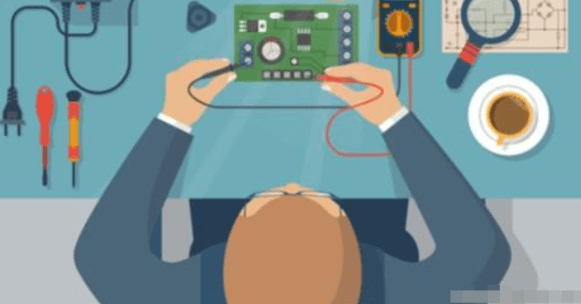
Multimeter probing can help you track down a short, but they are not always sensitive enough to find it.
Component Shorts
Checking components for shorts also requires measuring resistance with a multimeter. If a visual inspection does not reveal excess solder or metal flakes between pads, the short may have formed on an inner layer between two pads/pins on a component. Shorts can also occur between pads/pins on a component due to improper manufacturing. This is one reason PCBs should be subject to DFM and design rule checks; during manufacturing, pads and vias placed too close together can inadvertently create bridges and shorts.
Here you need to measure the resistance between pins on an IC or connector. Adjacent pins are particularly susceptible to shorts, but they are not the only place shorts can form. Check for low resistance between pads/pins and between ground connections. Check the resistance between the ground pad and other pins on connectors and ICs. Shown here is a USB connector.
Narrowing Down the Location
If you think you have a short between two conductors or between a conductor and ground, you can narrow down the location by checking nearby conductors. With one lead of the multimeter on the suspected short connection, move the other lead to a different nearby ground connection and check the resistance. You should see a change in resistance as you move to a ground connection farther away. If the resistance increases, move the ground lead away from the short. This can help narrow down the exact location of the short and may even narrow it down to a specific pair of pads/pins on a component.
Step 3: How to Find Faulty Components on Your PCB
Faulty components or incorrectly installed components can both be part of a short and create a number of problems on your board. Your component could be faulty or a knockoff, creating a short or stub appearance.
Bad Components
Some components have a tendency to break, such as electrolytic capacitors. If there is a suspect component, check it first. If you are unsure, you can usually do a quick Google search of the component you suspect of “failing” to see if it is a common problem. If you measure very low resistance between the two electrodes/pins (neither of them is a ground or power pin), you probably have a short caused by a burned-out component. This is a clear sign that the capacitor is bad. Once a capacitor is bad, or the voltage applied exceeds the breakdown threshold, the capacitor will also swell.

See the bump on the top of the capacitor? That’s a sign that the capacitor is bad.
Step 4: How to Destructively Test a PCB
Destructive testing is obviously a last resort. If you have access to an X-ray imaging device, then you can inspect the inside of the board without destroying it.
In the absence of X-ray equipment, you can start removing components and running the multimeter test again. This helps in two ways. First, it gives you easier access to the hot pads. Second, it eliminates the possibility that a faulty component is causing the short, allowing you to focus on the conductors. If you manage to narrow down the location of the short to a connection on the component (for example, between two pads), it may not be obvious if the component is defective or if there is a short inside the board. At this point, you may need to remove the component and inspect the pads on the board. Removing the component can test if the component itself is defective, or if the pads on the board are bridging internally.
If the location of the short (or possibly multiple shorts) remains elusive, you can cut the board open to try and narrow down where the short is. If you know the approximate location of the short, then you can cut a section off the board and repeat your multimeter test on that section. At this point, it’s possible to repeat the above test with the multimeter to check if there is a short in a specific location. If you’ve gotten to this point, then your short has been particularly elusive. This will at least allow you to narrow down your short to a specific area of the PCB.
When we checked our board for shorts, because we were a broke startup and didn’t include IR testing, all we could find was half of the board that had a short. So, we cut the board into quarters and tested each section. Back to the multimeter, confirmed that most sections didn’t have VCC and ground connected together. But that quarter of the PCB was a mysterious little black hole that we never got close to the short. We did switch manufacturers and got a test board on the next round of production, and our board happened to work fine.