PCB Salt Spray Testing: A Comprehensive Guide
1. Introduction
Printed Circuit Boards (PCBs) are essential components in modern electronics, used in everything from consumer electronics to aerospace applications. One of the critical challenges in PCB manufacturing is ensuring their reliability under harsh environmental conditions, particularly in corrosive environments. Salt spray testing (also known as salt fog testing) is a standardized method used to evaluate the corrosion resistance of PCBs and their surface finishes.
This article provides a detailed overview of PCB salt spray testing, including its purpose, testing standards, procedures, equipment, and interpretation of results. By understanding this testing method, manufacturers can improve PCB durability and performance in corrosive conditions.
2. Purpose of Salt Spray Testing for PCBs
Salt spray testing simulates the corrosive effects of marine and industrial environments on PCBs. The primary objectives include:
- Evaluating Corrosion Resistance: Determines how well PCB surface finishes (e.g., HASL, ENIG, OSP, immersion silver/tin) withstand salt-laden atmospheres.
- Quality Assurance: Ensures that PCBs meet industry standards and customer requirements.
- Comparative Analysis: Helps compare different surface finishes or protective coatings.
- Failure Analysis: Identifies potential weaknesses in PCB materials or manufacturing processes.
Since PCBs used in automotive, marine, or outdoor applications are exposed to moisture and salt, this test is crucial for long-term reliability.

3. Salt Spray Testing Standards
Several international standards define the procedures for salt spray testing. The most commonly used standards for PCB testing include:
3.1 ASTM B117
- Title: Standard Practice for Operating Salt Spray (Fog) Apparatus
- Scope: Provides guidelines for creating and maintaining a salt spray environment.
- Test Conditions:
- Salt solution: 5% NaCl
- pH: 6.5 to 7.2
- Temperature: 35°C (95°F)
- Duration: Typically 24 to 1000+ hours
3.2 IEC 60068-2-11 (Ka Test)
- Title: Environmental Testing – Salt Mist Test
- Scope: Evaluates corrosion resistance under controlled salt mist conditions.
- Key Parameters:
- Salt concentration: 5%
- Test duration: Varies (commonly 48 to 96 hours)
3.3 IPC-TM-650
- Title: Test Methods Manual by IPC
- Relevant Tests:
- Method 2.6.11 (Corrosion, Salt Spray)
- Evaluates solderability and surface finish integrity after exposure.
3.4 JIS Z 2371
- Title: Japanese Industrial Standard for Salt Spray Testing
- Scope: Similar to ASTM B117 but with slight variations in pH and spray collection rate.
These standards ensure consistency and repeatability in corrosion testing across different industries.
4. Salt Spray Testing Procedure
4.1 Test Preparation
- Sample Selection:
- PCBs with different surface finishes are selected.
- Test coupons or actual PCBs can be used.
- Cleaning:
- PCBs are cleaned to remove contaminants that could affect results.
- Masking (if required):
- Certain areas may be masked to evaluate localized corrosion.
4.2 Test Execution
- Salt Solution Preparation:
- 5% NaCl solution in deionized water.
- pH adjusted to 6.5–7.2 (using NaOH or HCl).
- Test Chamber Setup:
- Temperature maintained at 35°C.
- Nozzles atomize the salt solution into a fine mist.
- Exposure Duration:
- Tests typically run for 24, 48, 96, or 168 hours.
- Some harsh environment tests may extend to 1000+ hours.
- Monitoring:
- Chamber conditions (temperature, spray rate) are checked periodically.
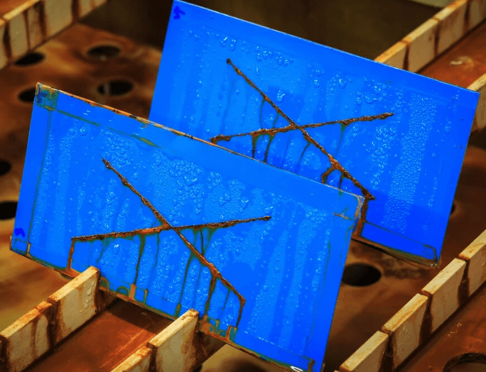
4.3 Post-Test Evaluation
After exposure, PCBs are inspected for:
- Visual Corrosion: Rust, discoloration, blistering.
- Electrical Performance: Continuity and insulation resistance tests.
- Solderability: If applicable, solder wetting is checked.
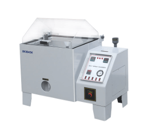
5. Equipment for Salt Spray Testing
A standard salt spray test chamber includes:
- Test Chamber: Corrosion-resistant (PVC or stainless steel).
- Salt Solution Reservoir: Holds the 5% NaCl solution.
- Atomizing Nozzles: Generates a fine salt mist.
- Heating System: Maintains constant temperature.
- Humidity Control: Ensures consistent fog density.
- Collection Funnel: Measures salt deposition rate.
Automated systems may include data logging for precise control.
6. Interpretation of Results
The test results are evaluated based on:
- Corrosion Rate: Time until first signs of corrosion appear.
- Extent of Damage: Percentage of surface affected.
- Functional Impact: Whether corrosion affects conductivity or solderability.
Pass/Fail Criteria:
- No visible corrosion after a specified duration (e.g., 96 hours).
- Minimal oxidation that does not impair functionality.
If a PCB fails, manufacturers may:
- Change the surface finish (e.g., switch from HASL to ENIG).
- Apply conformal coating for extra protection.
- Improve manufacturing processes (e.g., better cleaning).
7. Advantages and Limitations of Salt Spray Testing
7.1 Advantages
- Accelerated Testing: Simulates years of corrosion in days.
- Standardized: Follows globally recognized test methods.
- Cost-Effective: Helps prevent field failures before mass production.
7.2 Limitations
- Not Fully Realistic: Does not account for UV exposure, thermal cycling, or pollution variations.
- Subjective Evaluation: Visual inspection may vary between inspectors.
- Overestimation of Risk: Some PCBs may perform better in real-world conditions.
For comprehensive reliability testing, salt spray is often combined with humidity, thermal cycling, and vibration tests.
8. Alternative Corrosion Tests for PCBs
Since salt spray testing has limitations, other methods include:
- Humidity Testing (85°C/85% RH): Evaluates moisture resistance.
- Mixed Flowing Gas (MFG) Testing: Simulates industrial pollution.
- Electrochemical Impedance Spectroscopy (EIS): Measures coating degradation.
These tests provide a more complete picture of PCB durability.
9. Conclusion
Salt spray testing is a vital tool for assessing PCB corrosion resistance, particularly in harsh environments. By following standardized procedures (ASTM B117, IEC 60068-2-11, etc.), manufacturers can ensure their PCBs meet industry requirements. While the test has limitations, it remains a cost-effective way to screen for potential corrosion issues early in the design phase.
For optimal reliability, salt spray testing should be combined with other environmental tests. As PCB technology advances, continued improvements in surface finishes and protective coatings will further enhance corrosion resistance, ensuring longer-lasting electronic devices in demanding applications.