The Comprehensive Guide to PCB Hot Plates: Principles, Applications, and Best Practices
Introduction to PCB Hot Plates
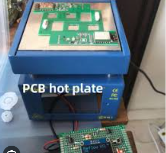
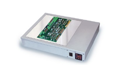
Printed Circuit Board (PCB) hot plates have become indispensable tools in modern electronics manufacturing and prototyping. These specialized heating devices provide precise temperature control for various PCB-related processes, offering superior performance compared to traditional heating methods. A PCB hot plate is essentially a flat, temperature-controlled surface designed specifically for heating PCBs during soldering, reflow, component removal, or other thermal processes.
The evolution of PCB hot plates has paralleled the advancement of electronic components. As devices have become smaller and more complex, the need for precise, localized heating has grown exponentially. Traditional soldering irons, while effective for through-hole components, often prove inadequate for surface-mount technology (SMT) work or board-level heating. This technological gap led to the development of specialized hot plates that could provide uniform heating across entire PCBs.
Modern PCB hot plates offer numerous advantages:
- Precise temperature control (typically within ±1°C)
- Large, uniform heating surfaces
- Programmable temperature profiles
- Safety features for sensitive components
- Compatibility with lead-free soldering processes
These features make PCB hot plates essential for electronics manufacturing, repair stations, research labs, and educational institutions working with modern circuit boards.
Working Principles of PCB Hot Plates
Heating Mechanism
PCB hot plates operate on relatively straightforward thermal principles but incorporate sophisticated control systems to achieve their precision. The core heating element is typically made of:
- Metal Alloy Plates: Often aluminum or stainless steel for good thermal conductivity and durability
- Embedded Heating Elements: Usually resistive wire or etched foil patterns
- Insulation Layers: To direct heat upward and improve efficiency
The heating process follows these stages:
- Power Application: Electricity flows through the resistive heating elements
- Heat Generation: Resistance converts electrical energy to thermal energy
- Heat Distribution: The metal plate spreads heat evenly across its surface
- Temperature Regulation: Sensors provide feedback to maintain set temperatures
Temperature Control Systems
Advanced PCB hot plates employ PID (Proportional-Integral-Derivative) control algorithms to maintain exceptionally stable temperatures. This system:
- Measures actual plate temperature via thermocouples or RTDs
- Compares it to the user-set target temperature
- Calculates the necessary power adjustment
- Adjusts current to the heating elements accordingly
This closed-loop control allows for temperature stability within 1-2°C, crucial for sensitive electronic work.
Heat Transfer Methods
PCB hot plates primarily use conduction for heat transfer:
- Direct Conduction: The PCB sits directly on the heated surface
- Air Gap Conduction: Some systems use small air gaps for gentler heating
- Assisted Convection: Some models incorporate fans for more even heating
The efficiency of heat transfer depends on:
- Surface flatness and smoothness
- Thermal conductivity of materials
- Contact area between PCB and plate
- Applied pressure (if any)
Types of PCB Hot Plates
By Heating Technology
- Standard Thermal Hot Plates:
- Resistive heating elements
- Temperature range: 50°C to 450°C
- Most common for general PCB work
- Ceramic Hot Plates:
- Use PTC (Positive Temperature Coefficient) ceramic elements
- More uniform heating
- Faster response times
- Induction Hot Plates:
- Use electromagnetic induction to heat the plate
- Very rapid heating
- More complex control systems
By Application
- Soldering Hot Plates:
- Optimized for solder reflow
- Typical range: 180°C-300°C
- Often include solder paste stencil alignment features
- Desoldering/Repair Hot Plates:
- Higher temperature capabilities (up to 450°C)
- Larger surface areas for full-board heating
- Precise control for component removal
- Prototyping Hot Plates:
- Smaller sizes for individual boards
- Programmable temperature profiles
- Often include magnification or lighting
By Size and Capacity
| Type | Size Range | Typical Capacity | Best For |
|---|---|---|---|
| Benchtop | 200x200mm to 400x400mm | 1-4 standard PCBs | Small labs, repair shops |
| Production | 500x500mm and larger | Multiple panels | Manufacturing settings |
| Portable | 100x100mm to 150x150mm | Small boards | Field work, education |
Key Applications of PCB Hot Plates
PCB Assembly and Soldering
- Reflow Soldering:
- Melting solder paste to attach SMD components
- Requires precise temperature profiles
- Alternative to oven reflow for small batches
- Hand Soldering Assistance:
- Preheating boards reduces thermal stress
- Allows easier soldering of ground planes
- Improves solder joint quality
- Stencil Alignment:
- Heating helps secure PCBs during paste application
- Reduces movement during stencil removal
PCB Rework and Repair
- Component Removal:
- Heating entire boards for safe IC removal
- Reducing stress on pads and traces
- Eliminating need for multiple heat guns
- BGA Rework:
- Bottom-side heating during BGA operations
- Preventing board warping
- Maintaining proper temperature gradients
- Adhesive Curing:
- Setting glues and epoxies
- Accelerating curing processes
- Ensuring uniform adhesive properties
Specialized Processes
- PCB Baking:
- Removing moisture before assembly
- Preventing “popcorning” during reflow
- Typically at lower temperatures (80°C-125°C)
- Conformal Coating:
- Accelerating coating curing
- Improving coating adhesion
- Reducing curing inconsistencies
- Thermal Testing:
- Environmental stress testing
- Thermal cycling experiments
- Failure analysis procedures
Advantages Over Alternative Heating Methods
Compared to Soldering Irons
- Area Heating: Entire board vs. single joints
- Thermal Stress Reduction: Gradual heating prevents shock
- Consistency: Uniform temperature across components
- Efficiency: Faster processing of multiple joints
Compared to Reflow Ovens
- Cost: Significantly lower initial investment
- Space: Compact benchtop footprint
- Flexibility: Easier for small batches or prototypes
- Visibility: Direct observation of soldering process
Compared to Heat Guns
- Precision: Exact temperature control
- Safety: No risk of blown components
- Repeatability: Consistent results
- Protection: No direct airflow on components
Technical Specifications and Selection Criteria
Critical Specifications
- Temperature Range:
- Standard: 50°C to 450°C
- Specialized: Up to 600°C for high-temp applications
- Temperature Stability:
- Basic: ±5°C
- Precision: ±1°C or better
- Heating Area:
- Small: 100x100mm
- Medium: 200x200mm to 300x300mm
- Large: 400x400mm and above
- Heating Time:
- Time to reach 300°C from room temperature
- Ranges from 2-15 minutes depending on size
- Power Requirements:
- Small: 200-500W
- Medium: 600-1200W
- Large: 1500W and above
Selection Considerations
- Board Size:
- Choose a plate at least 20% larger than your largest PCB
- Temperature Needs:
- Standard soldering: 250°C-300°C
- Lead-free: May require 300°C-350°C
- Special alloys: Verify temperature requirements
- Control Features:
- Digital vs. analog controls
- Programmable profiles
- Memory functions
- Safety Features:
- Over-temperature protection
- Automatic shut-off
- Insulated surfaces
- Accessories:
- PCB holders
- Magnification lenses
- Fume extraction options
Best Practices for PCB Hot Plate Usage
Setup and Calibration
- Initial Setup:
- Place on stable, heat-resistant surface
- Ensure proper ventilation
- Verify electrical requirements
- Calibration:
- Use external thermocouple to verify temperatures
- Check multiple points for uniformity
- Recalibrate periodically (every 6-12 months)
- Surface Preparation:
- Keep surface clean and smooth
- Use Kapton tape if needed for protection
- Apply thermal interface materials if necessary
Operating Procedures
- Preheating:
- Allow plate to stabilize at target temperature
- Larger plates may need longer stabilization
- Board Placement:
- Center PCB on heating surface
- Use standoffs for double-sided boards
- Secure large boards if needed
- Temperature Profiling:
- For reflow, follow solder paste specifications
- Typically: ramp-up, soak, reflow, cooling stages
- Monitor with external thermocouple if possible
Safety Considerations
- Personal Protection:
- Heat-resistant gloves
- Safety glasses
- Fume extraction for soldering
- Work Area Safety:
- Fire-resistant surface
- Clear of flammable materials
- Emergency shut-off accessible
- Equipment Safety:
- Don’t exceed maximum temperature ratings
- Avoid thermal shock (rapid temperature changes)
- Regular inspection of power cords
Maintenance
- Cleaning:
- Regular removal of flux residues
- Non-abrasive cleaners only
- Immediate cleaning of spills
- Component Checks:
- Inspect heating elements periodically
- Verify sensor accuracy
- Check for loose connections
- Storage:
- Cool completely before storage
- Cover when not in use
- Store in dry environment
Emerging Trends and Future Developments
Smart Hot Plate Technology
- IoT Integration:
- Remote monitoring and control
- Usage tracking and analytics
- Predictive maintenance features
- Advanced Controls:
- AI-based temperature optimization
- Automatic profile generation
- Component recognition systems
- Enhanced Safety Systems:
- Automatic fault detection
- Improved fume handling
- Better insulation technologies
Material Innovations
- Graphene Heating Elements:
- Faster heating times
- Improved temperature uniformity
- Longer lifespan
- Advanced Composites:
- Higher temperature capabilities
- Better thermal conductivity
- Reduced weight
- Self-cleaning Surfaces:
- Non-stick coatings
- Easy flux removal
- Scratch-resistant materials
Application Expansions
- Flexible PCB Support:
- Curved heating surfaces
- Lower temperature options
- Specialized holders
- High-Density Interconnect (HDI) Applications:
- Precision micro-heating zones
- Ultra-stable temperature control
- Miniaturized systems
- Educational Kits:
- Affordable, student-grade models
- Integrated learning systems
- Curriculum-focused designs
Conclusion
PCB hot plates have evolved from simple heating devices to sophisticated thermal management systems that address the complex needs of modern electronics manufacturing and repair. Their ability to provide precise, controlled heating makes them invaluable for everything from prototype development to high-volume production.
When selecting and using a PCB hot plate, professionals must consider:
- The specific thermal requirements of their applications
- The size and complexity of their PCBs
- The necessary safety and control features
- The total cost of ownership including maintenance
As electronic components continue to shrink and become more thermally sensitive, the role of PCB hot plates will only grow in importance. Future advancements in materials science, control systems, and smart technologies promise to make these tools even more precise, efficient, and user-friendly.
Whether you’re a hobbyist working on occasional projects or an electronics manufacturer running production lines, understanding and properly utilizing PCB hot plate technology can significantly improve your work quality, efficiency, and reliability. By following best practices and staying informed about new developments, users can maximize the benefits of these essential tools in the ever-evolving world of electronics.