PCB Motor: Design, Applications, and Future Prospects
Introduction to PCB Motor Technology
Printed Circuit Board (PCB) motors represent a revolutionary advancement in electromechanical systems, combining the principles of traditional electric motors with modern printed circuit board manufacturing techniques. These innovative devices integrate both the electrical and mechanical components of a motor directly onto a PCB substrate, creating a compact, lightweight, and highly efficient motion solution.
PCB motors, also known as planar motors or printed motors, eliminate many of the bulky components found in conventional motors by leveraging the multilayer capabilities of modern PCBs. The windings are printed directly onto the board as copper traces, while permanent magnets are mounted on the moving part (rotor or slider). This unique architecture offers several advantages over traditional motors, including reduced size and weight, lower manufacturing costs at scale, and the ability to create completely flat motor designs.
The concept of PCB motors emerged from the need for miniaturized motion solutions in modern electronics. As devices became smaller and more compact, traditional motors often proved too bulky or inefficient for certain applications. PCB technology provided an elegant solution by allowing motor components to be integrated directly into the device’s existing circuit board infrastructure.
Working Principles of PCB Motors
PCB motors operate on the same fundamental electromagnetic principles as conventional motors but implement these principles in a radically different physical configuration. The basic working mechanism involves the interaction between current-carrying conductors (the PCB traces) and permanent magnets to generate mechanical motion.
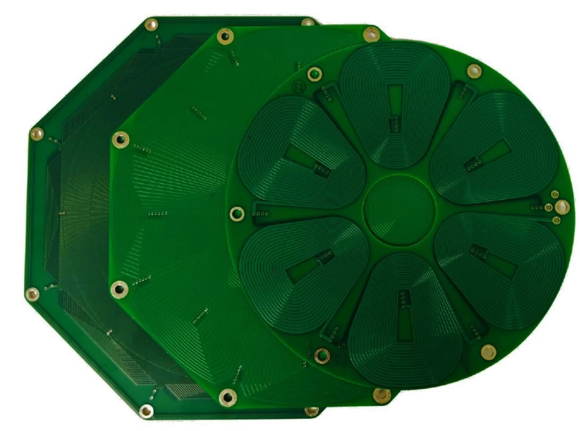
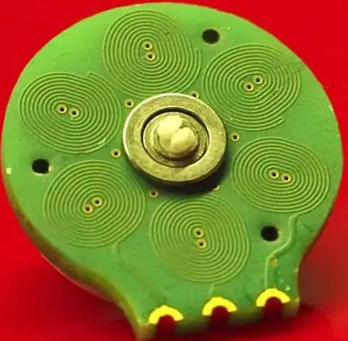
In a typical PCB motor design, the stator consists of multiple layers of carefully patterned copper traces on the PCB that function as the motor windings. These traces are arranged in specific geometric patterns to create magnetic fields when energized. The rotor (in rotary designs) or slider (in linear designs) contains an array of permanent magnets that interact with these magnetic fields to produce motion.
There are several types of PCB motors, each with distinct operational characteristics:
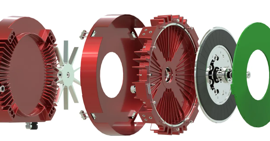
- Axial Flux PCB Motors: In this configuration, the magnetic flux runs parallel to the motor’s axis of rotation. The PCB contains spiral or concentric winding patterns that face a rotor disc equipped with permanent magnets.
- Linear PCB Motors: These create straight-line motion rather than rotation. The “stator” is a flat PCB with a sequence of traces, while the moving part contains magnets that are propelled along the length of the board.
- Planar Motors: These can produce motion in two dimensions across a flat surface, with multiple PCB winding sections enabling movement in both X and Y directions.
The control of PCB motors typically requires specialized driver electronics that can precisely sequence the activation of the various winding sections. This is often accomplished through H-bridge circuits or more advanced motor driver ICs that can handle the specific requirements of the PCB winding configuration.
Design Considerations for PCB Motors
Designing an effective PCB motor requires careful consideration of numerous factors that influence performance, efficiency, and reliability:
1. Trace Geometry and Layout:
The pattern of copper traces on the PCB is critical to motor performance. Designers must optimize:
- Trace width and thickness (affects current capacity and resistance)
- Spacing between traces (prevents shorting and controls magnetic field distribution)
- Overall winding pattern (determines magnetic field characteristics)
- Number of layers (more layers can increase power but add complexity)
2. Material Selection:
- Substrate material (typically FR4, but high-temperature or flexible materials may be used)
- Copper weight (thicker copper allows higher current but affects manufacturability)
- Magnet type (neodymium magnets are common for their strong magnetic fields)
3. Thermal Management:
PCB motors can generate significant heat due to resistive losses in the traces. Design considerations include:
- Thermal vias to dissipate heat
- Copper pour areas for heat spreading
- Potential for additional cooling methods in high-power designs
4. Electromagnetic Optimization:
- Minimizing eddy current losses
- Reducing electromagnetic interference (EMI)
- Optimizing the magnetic circuit for maximum efficiency
5. Mechanical Integration:
- Bearing selection and placement
- Air gap between PCB and magnets
- Structural support for moving components
- Vibration and noise reduction
Advanced simulation tools are often employed in PCB motor design, including finite element analysis (FEA) for electromagnetic and thermal modeling, as well as mechanical simulation software to evaluate structural integrity and motion characteristics.
Manufacturing Process of PCB Motors
The manufacturing of PCB motors combines standard printed circuit board fabrication techniques with specialized assembly processes:
1. PCB Fabrication:
- Multilayer board lamination
- Precise copper etching to create winding patterns
- Via formation for interlayer connections
- Surface finish application (often ENIG or HASL)
2. Component Assembly:
- Solder paste application
- Placement of electronic components (sensors, connectors, etc.)
- Reflow soldering
- Potential for selective hand assembly of sensitive components
3. Magnet Assembly:
- Precise placement of permanent magnets
- Adhesive bonding or mechanical fastening
- Magnetization (if not pre-magnetized)
4. Final Assembly:
- Integration of mechanical components (bearings, shafts, etc.)
- Alignment of moving parts
- Quality testing and performance verification
The manufacturing process benefits from the established infrastructure of PCB production, allowing for potentially lower costs at scale compared to traditional motor manufacturing. However, the magnet assembly and mechanical integration steps often require specialized tooling and careful quality control.
Applications of PCB Motors
PCB motors find applications across numerous industries where their unique characteristics provide significant advantages:
1. Consumer Electronics:
- Smartphone camera lens actuators
- Vibration motors in wearables
- Miniature cooling fans for compact devices
2. Medical Devices:
- Drug delivery pumps
- Surgical robotics
- Portable medical equipment requiring compact motion solutions
3. Automotive Systems:
- HVAC actuators
- Sensor positioning mechanisms
- Emerging applications in electric vehicles
4. Aerospace and Defense:
- Satellite component positioning
- UAV control surfaces
- Lightweight actuators for space-constrained applications
5. Industrial Automation:
- Precision linear stages
- Compact robotics
- Semiconductor manufacturing equipment
6. IoT and Smart Devices:
- Smart home actuators
- Agricultural sensor positioning systems
- Environmental monitoring equipment
The flat profile and integration capabilities of PCB motors make them particularly valuable in applications where space is at a premium or where traditional motors would be prohibitively bulky. Their ability to be manufactured using standard PCB processes also makes them attractive for applications requiring cost-effective, high-volume production.
Advantages and Limitations of PCB Motors
Advantages:
- Compact Size and Low Profile: PCB motors can be extremely thin and lightweight, enabling integration into space-constrained applications.
- Design Flexibility: The PCB manufacturing process allows for complex winding patterns that would be difficult or impossible with traditional wire windings.
- Precision Control: The distributed nature of PCB windings enables fine control over motion characteristics.
- Integration Potential: Electronic components can be mounted directly on the same board, reducing system complexity.
- Scalable Manufacturing: PCB production techniques allow for cost-effective volume manufacturing.
- Customizability: Winding patterns can be easily modified between production runs to optimize for different performance characteristics.
Limitations:
- Power Density: PCB motors typically have lower power density compared to traditional motors due to limitations in current-carrying capacity of PCB traces.
- Thermal Challenges: Heat dissipation can be problematic in high-current applications due to the limited thermal mass of PCBs.
- Torque/Speed Limitations: The planar design imposes certain constraints on torque production and maximum speed compared to conventional motor geometries.
- Mechanical Complexity: Integrating bearings and other mechanical components with the PCB can present design challenges.
- Material Constraints: Standard PCB materials may not be suitable for high-temperature or high-vibration environments without special considerations.
Future Developments in PCB Motor Technology
The field of PCB motor technology continues to evolve rapidly, with several promising directions for future development:
1. Advanced Materials:
- Higher-temperature substrates for improved thermal performance
- Embedded cooling solutions (such as microfluidic channels)
- Nanocomposite materials for enhanced magnetic properties
2. Manufacturing Innovations:
- Additive manufacturing techniques for complex 3D PCB motor structures
- Integration with flexible and stretchable electronics
- Automated assembly processes for higher-volume production
3. Improved Design Tools:
- AI-assisted optimization of winding patterns
- Advanced simulation capabilities for multiphysics modeling
- Digital twin technology for virtual prototyping
4. New Applications:
- Biomedical implants requiring ultra-flat actuators
- Soft robotics utilizing flexible PCB motors
- Space applications benefiting from lightweight designs
5. Enhanced Performance:
- Higher power density through improved thermal management
- Integrated sensing and control electronics
- Hybrid designs combining PCB and traditional motor elements
As these developments progress, PCB motors are expected to find adoption in an even broader range of applications, potentially displacing traditional motors in many areas where compact size, low weight, and integration capabilities are prioritized over raw power output.
Conclusion
PCB motor technology represents a significant convergence of electrical and mechanical engineering, leveraging advanced PCB manufacturing techniques to create innovative motion solutions. While these motors may not replace traditional designs in all applications, they offer compelling advantages for space-constrained, weight-sensitive, or highly integrated systems.
The continued advancement of PCB materials, manufacturing processes, and design tools promises to expand the capabilities and applications of PCB motors in the coming years. As industries increasingly demand compact, efficient, and intelligent motion solutions, PCB motors are well-positioned to play a growing role in everything from consumer electronics to advanced industrial systems.
For engineers and product designers, understanding PCB motor technology provides access to a new toolkit of motion solutions that can enable innovative product designs and overcome space limitations that would be insurmountable with conventional motor technologies. As the technology matures, we can expect to see PCB motors become an increasingly common solution across a wide spectrum of electromechanical systems.