PCB Soldering and Desoldering Techniques: A Comprehensive Guide
Introduction to PCB Soldering
Printed Circuit Board (PCB) soldering is a fundamental skill in electronics manufacturing, repair, and prototyping. This essential process involves joining electronic components to the conductive pads on a PCB using molten metal alloy (solder) to create permanent electrical connections. Mastering PCB soldering and desoldering techniques is crucial for anyone working with electronic circuits, from professional technicians to hobbyists.
Soldering creates reliable electrical connections while providing sufficient mechanical strength to hold components in place. The quality of solder joints directly affects the performance and longevity of electronic devices. Poor soldering can lead to intermittent connections, increased resistance, or complete circuit failure.
Essential Tools for PCB Soldering
1. Soldering Irons
The soldering iron is the primary tool for PCB work. Key considerations include:
- Wattage: 15-60 watts for most PCB work
- Temperature control: Adjustable temperature (300-400°C) is preferable
- Tip selection: Various shapes (conical, chisel, bevel) for different tasks
- ESD-safe: Important for sensitive components
2. Solder Materials
- Lead-based solder (Sn60/Pb40): Easier to work with but being phased out due to environmental concerns
- Lead-free solder (Sn96.5/Ag3/Cu0.5): Requires higher temperatures but more environmentally friendly
- Solder wire diameters: 0.5mm-1.0mm for most PCB work
- Flux-core solder: Contains flux that cleans surfaces during soldering
3. Additional Tools
- Soldering stand with sponge or brass wool
- Tweezers (non-magnetic preferred)
- Wire cutters and strippers
- Magnifying glass or microscope for inspection
- Desoldering tools (pump, wick, etc.)
- Fume extractor or well-ventilated area
Basic PCB Soldering Techniques
1. Preparation
- Clean the PCB and component leads
- Ensure proper component placement
- Secure the PCB in a stable position
- Preheat the soldering iron to appropriate temperature
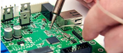
2. Through-Hole Component Soldering
- Insert the component leads through the PCB holes
- Bend leads slightly to hold components in place
- Apply the soldering iron tip to both the pad and lead simultaneously
- Feed solder to the joint (not directly to the iron)
- Allow solder to flow evenly around the joint
- Remove solder first, then the iron
- Let the joint cool undisturbed
- Trim excess lead length
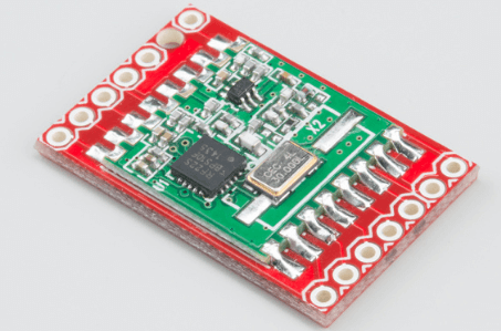
3. Surface Mount Device (SMD) Soldering
- Hand soldering:
- Apply flux to the pads
- Position the component carefully
- Tack one pad to hold the component
- Solder remaining pins
- Inspect for bridges or insufficient solder
- Hot air rework:
- Apply solder paste to pads
- Position components
- Use hot air station with appropriate nozzle
- Heat evenly until solder flows
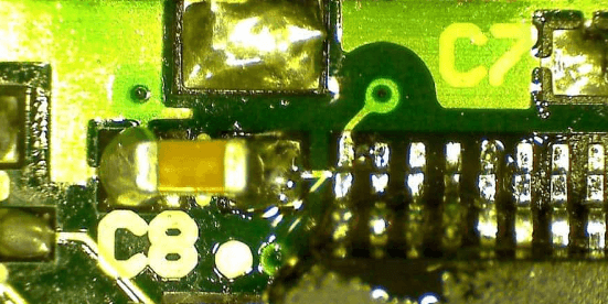
4. Creating Proper Solder Joints
A good solder joint should:
- Be shiny and smooth (not dull or grainy)
- Form a concave fillet between lead and pad
- Cover the pad completely without bridging
- Show no cracks or voids
Common Soldering Problems and Solutions
1. Cold Joints
- Appearance: Dull, lumpy, grainy surface
- Cause: Insufficient heat or movement during cooling
- Solution: Reheat and add fresh solder if needed
2. Solder Bridges
- Appearance: Unintended connections between pads
- Cause: Excess solder or improper technique
- Solution: Use solder wick or pump to remove excess
3. Insufficient Wetting
- Appearance: Solder doesn’t flow properly on surfaces
- Cause: Dirty surfaces or insufficient heat
- Solution: Clean surfaces and ensure proper temperature
4. Lifted Pads
- Appearance: Pad separates from PCB
- Cause: Excessive heat or mechanical stress
- Solution: Repair with jumper wire if possible
PCB Desoldering Techniques
1. Solder Sucker (Desoldering Pump)
- Heat the existing solder joint
- Quickly position the pump nozzle
- Release the plunger to suck molten solder
- Repeat if necessary
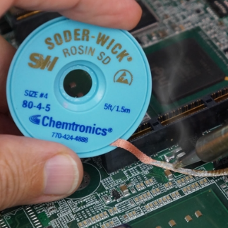
2. Desoldering Braid (Solder Wick)
- Place braid over the solder joint
- Apply soldering iron on top
- Solder will wick into the braid
- Move to clean sections as needed
3. Hot Air Rework Station
- Select appropriate nozzle
- Set temperature and airflow
- Heat the area evenly
- Remove component when solder melts
4. Chip Quik or Low-Temperature Alloy
- Apply special alloy to lower melting point
- Keep all pins molten simultaneously
- Gently remove the component
Advanced Techniques
1. BGA (Ball Grid Array) Rework
- Requires precise temperature control
- Uses specialized equipment (BGA station)
- Often includes stencils for ball replacement
- X-ray inspection may be necessary
2. QFN (Quad Flat No-Lead) Packages
- Challenging due to hidden ground pads
- May require preheating the PCB
- Hot air with proper nozzles is essential
3. Micro-soldering
- For extremely small components (0201, 01005 sizes)
- Requires high magnification
- Uses micro-tips and fine solder
Safety Considerations
- Ventilation: Always work in well-ventilated areas to avoid inhaling fumes
- Eye protection: Wear safety glasses to prevent splashes
- ESD protection: Use grounded mats and wrist straps for sensitive components
- Burn prevention: Be cautious of hot tools and molten solder
- Chemical safety: Handle flux and cleaning solvents properly
Maintenance of Soldering Equipment
- Tip care:
- Keep tips properly tinned
- Clean regularly with damp sponge or brass wool
- Use appropriate temperature settings
- Iron maintenance:
- Replace heating elements as needed
- Store properly when not in use
- Avoid mechanical stress on tips
- Tool organization:
- Keep work area clean and organized
- Store tools properly to prevent damage
Industry Standards and Best Practices
- IPC standards:
- IPC-A-610: Acceptability of Electronic Assemblies
- IPC-J-STD-001: Requirements for Soldered Electrical Connections
- Quality control:
- Visual inspection under magnification
- Automated optical inspection (AOI) in production
- X-ray inspection for hidden joints (BGAs)
- Process control:
- Temperature profiling
- Solder paste management
- Equipment calibration
Practical Exercises for Skill Development
- Beginner exercises:
- Soldering wires together
- Through-hole resistor placement
- Simple SMD components (0805, 1206 sizes)
- Intermediate exercises:
- Multi-pin ICs (SOIC, QFP packages)
- Connector soldering
- Desoldering and replacement
- Advanced exercises:
- Fine-pitch components (0.5mm pitch or less)
- BGA reballing and replacement
- Micro-soldering techniques
Future Trends in PCB Soldering
- Miniaturization:
- Smaller components requiring advanced techniques
- Increased use of micro-soldering
- Automation:
- Robotic soldering systems
- Machine vision for quality control
- Materials development:
- New solder alloys with improved properties
- Advanced flux formulations
- Environmental considerations:
- Continued move to lead-free processes
- Reduced use of hazardous materials
Conclusion
Mastering PCB soldering and desoldering techniques requires both theoretical knowledge and practical experience. By understanding the principles, using proper tools, and following best practices, technicians can create reliable electronic assemblies and perform effective repairs. Continuous practice and staying updated with industry developments are essential for maintaining and improving these crucial skills in the ever-evolving field of electronics manufacturing and repair.
Remember that quality soldering is both an art and a science—while the technical aspects can be learned, developing the “feel” for good soldering comes with experience. Whether you’re a professional technician or an electronics hobbyist, investing time in perfecting your soldering skills will pay dividends in the quality and reliability of your work.