Metal Core PCB: Structure, Design Considerations, and Key Notes
1. Introduction
Printed Circuit Boards (PCBs) are essential components in modern electronics, providing mechanical support and electrical connections. Among various PCB types, Metal Core PCBs (MCPCBs) are widely used in high-power and high-temperature applications due to their superior thermal management capabilities.
MCPCBs incorporate a metal substrate (typically aluminum or copper) instead of traditional FR4 material, significantly improving heat dissipation. This article explores the structure of MCPCBs, key design considerations, and important manufacturing and assembly guidelines.
2. Structure of Metal Core PCBs
A standard MCPCB consists of multiple layers, each serving a specific purpose:
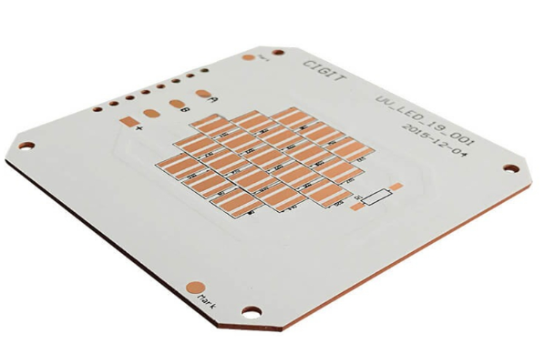
2.1 Metal Core (Base Layer)
- The base layer is typically made of aluminum (Al), copper (Cu), or a combination of both.
- Aluminum MCPCBs are cost-effective and widely used in LED lighting, power supplies, and automotive electronics.
- Copper MCPCBs offer better thermal conductivity but are more expensive, making them suitable for high-power RF and military applications.
2.2 Dielectric Layer (Thermal Insulation Layer)
- A thin dielectric layer (usually polyimide or epoxy-based) is laminated onto the metal core to provide electrical insulation while allowing heat transfer.
- The thermal conductivity of this layer (measured in W/mK) is critical—higher values improve heat dissipation.
2.3 Copper Circuit Layer
- A thin copper foil (typically 1 oz to 4 oz) is etched to form the conductive traces.
- Thicker copper layers enhance current-carrying capacity but may require adjustments in etching and soldering processes.
2.4 Solder Mask & Silkscreen
- A solder mask (usually green, black, or white) is applied to prevent short circuits.
- Silkscreen markings (component labels, logos) are printed for assembly guidance.
3. Design Considerations for Metal Core PCBs
Designing an MCPCB requires careful attention to thermal, electrical, and mechanical factors. Below are the key considerations:
3.1 Thermal Management
- Heat Dissipation Path: Ensure the metal core effectively transfers heat away from critical components (e.g., power transistors, LEDs).
- Thermal Vias: Use thermal vias (plated holes) to enhance heat transfer between layers in multilayer MCPCBs.
- Component Placement: Position high-heat components directly over the metal core for optimal cooling.
3.2 Copper Trace Layout
- Wider Traces for High Current: Thicker traces reduce resistance and prevent overheating.
- Avoid Sharp Corners: Use curved or 45° angles to minimize electromagnetic interference (EMI) and improve signal integrity.
3.3 Dielectric Material Selection
- Choose a dielectric with high thermal conductivity (e.g., Bergquist’s Thermal Clad, Laird Technologies’ Tlam™).
- Ensure the material can withstand high voltages if used in power electronics.
3.4 Mechanical Design Factors
- Board Thickness: Standard MCPCB thickness ranges from 0.8 mm to 3.0 mm, depending on thermal and mechanical requirements.
- Mounting Holes: Metal cores expand with heat, so allow sufficient clearance to avoid stress cracks.
3.5 Solder Mask & Surface Finish
- Solder Mask: Use high-temperature resistant masks to withstand reflow soldering.
- Surface Finish: Common options include:
- HASL (Hot Air Solder Leveling) – Cost-effective but not ideal for fine-pitch components.
- ENIG (Electroless Nickel Immersion Gold) – Better for high-frequency and corrosion-resistant applications.
- OSP (Organic Solderability Preservative) – Suitable for short shelf-life boards.
4. Manufacturing & Assembly Notes
4.1 Fabrication Challenges
- Metal Core Drilling: Requires specialized carbide or diamond-coated drill bits due to hardness.
- Layer Misalignment: Tight tolerances are needed to ensure proper registration between layers.
- Warpage Control: Uneven thermal expansion can cause bending; proper lamination processes are crucial.
4.2 Assembly Guidelines
- Reflow Soldering: Use low-stress profiles to avoid delamination.
- Handling & Storage: MCPCBs are heavier than FR4 PCBs—ensure proper support during assembly.
- Thermal Paste Application: For components requiring extra cooling (e.g., high-power LEDs), apply thermal paste between the PCB and heat sink.
5. Applications of Metal Core PCBs
MCPCBs are ideal for applications requiring efficient heat dissipation:
- LED Lighting (Streetlights, automotive LEDs)
- Power Electronics (Inverters, motor controllers)
- Automotive Systems (Battery management, headlights)
- RF & Microwave Devices (High-frequency amplifiers)
- Industrial Equipment (Power converters, welding machines)
6. Conclusion
Metal Core PCBs offer superior thermal performance compared to traditional FR4 boards, making them indispensable in high-power applications. Designers must carefully consider thermal management, material selection, and manufacturing constraints to ensure reliability. By following best practices in trace routing, dielectric choice, and assembly techniques, engineers can maximize the efficiency and longevity of MCPCB-based systems.
As electronics continue to demand higher power densities, MCPCB technology will evolve, incorporating advanced materials like ceramic-filled dielectrics and hybrid metal cores for even better performance.