What is the CAF effect of PCB?
Conductive Anodic Filament (CAF) Phenomenon and Its Impact
In the manufacturing of high-tech electronic products, especially in the automotive electronics and military fields with extremely high requirements for environmental adaptability, the high temperature and high humidity resistance of the products are particularly important. As electronic products develop towards higher integration, the hole spacing on the circuit board continues to shrink, and the reliability requirements for the holes are also increasing. In this context, the conductive anodic filament (CAF) phenomenon has become a key issue affecting the reliability of electronic equipment.
The CAF phenomenon refers to the migration of copper ions through tiny cracks between glass fiber filaments to low voltage areas under high voltage inside the PCB (printed circuit board) to form a conductive path. In a high temperature and high humidity environment, if the PCB or PCBA (printed circuit board assembly) is charged, CAF may be formed between the insulated conductors, resulting in reduced insulation performance and even short circuits, which seriously affect the performance and safety of the equipment.
Detection and Analysis of CAF Phenomenon
In order to effectively detect and analyze the CAF phenomenon, technicians will use the method of longitudinal grinding of the PCB and use an electron microscope for magnified observation. In the 100x magnified view, the dark areas of the material and the bright gold parts of the copper can be clearly seen. In the area between the vias, the presence of the CAF phenomenon can be confirmed by the observed copper dots or copper wires, which are the direct cause of the reduced insulation performance. Through this careful observation and analysis, manufacturers can deeply understand the causes of the CAF phenomenon and take preventive and improvement measures to improve the reliability and safety of products and meet the strict requirements of specific industries for electronic equipment in high temperature and high humidity environments.
Mechanism of the generation of CAF phenomenon
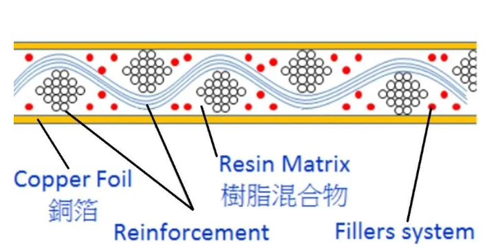
The material and structure of the PCB have a decisive influence on its performance. FR4 is the most common type of PCB substrate material, which consists of glass fiber cloth and epoxy resin. During the manufacturing process, the glass fiber is woven into cloth and then coated with semi-cured epoxy resin. If the adhesion between the epoxy resin and the glass fiber is insufficient, or there is a problem in the resin impregnation process, a gap may form between the two.
Under high temperature and high humidity environment, the adhesion between epoxy resin and glass fiber may further deteriorate, causing the silane coupling agent on the surface of glass fiber to undergo hydrolysis reaction, forming an electrochemical migration path, that is, the migration channel of copper ions.
Growth of conductive anode wire
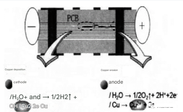
Once the ion migration channel is formed and there is a potential difference between the two insulating holes, the copper on the anode will be oxidized to copper ions and migrate to the cathode under the action of the electric field. During the migration process, the copper ions combine with the impurity ions or OH- in the board to form a water-insoluble conductive salt, which is deposited, causing the electrical spacing between the two insulating holes to drop sharply, and even directly conduct to form a short circuit.
Influence of PCB design
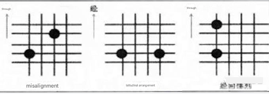
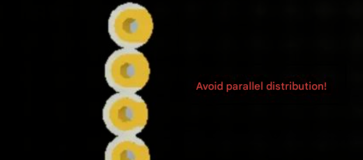
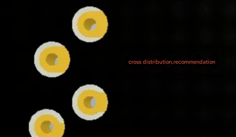
The hole arrangement in PCB design has a significant impact on CAF performance. Displacement arrangement, weft arrangement and warp arrangement are three basic arrangement methods, and their effects on CAF performance decrease in turn. When designing PCBs, manufacturers should consider the arrangement of holes and reduce the occurrence of CAF by optimizing the layout of holes to ensure the stable operation of electronic equipment under various environmental conditions.
The impact of PCB processing
During the PCB manufacturing process, the tiny gaps between the glass fiber and the resin have a significant impact on the CAF performance. The pressing process parameters, the degumming process and the roughness of the hole wall are the key factors affecting the generation and development of CAF.
Differences in board formulations
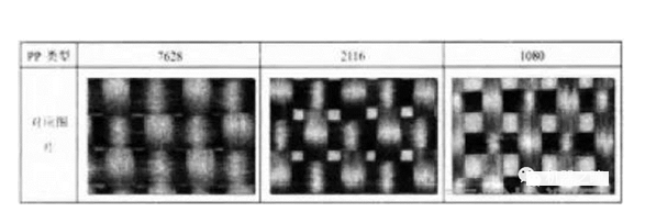
Copper clad laminates are pressed from prepreg and copper foil. The CAF performance of different prepregs varies greatly, which mainly depends on the weaving structure of the glass fiber cloth used.
Failure analysis method
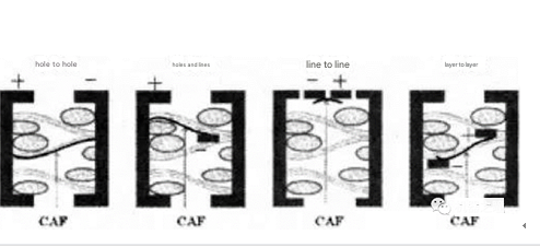
CAF phenomenon usually occurs between PTH holes and PTH holes, PTH holes and wires, wires and wires, and layers and layers. Jinjian Laboratory provides professional failure analysis services to help customers understand the internal structure of the circuit board and formulate appropriate analysis methods based on the structure, which is crucial for accurately analyzing the cause of failure.
Location of failure point
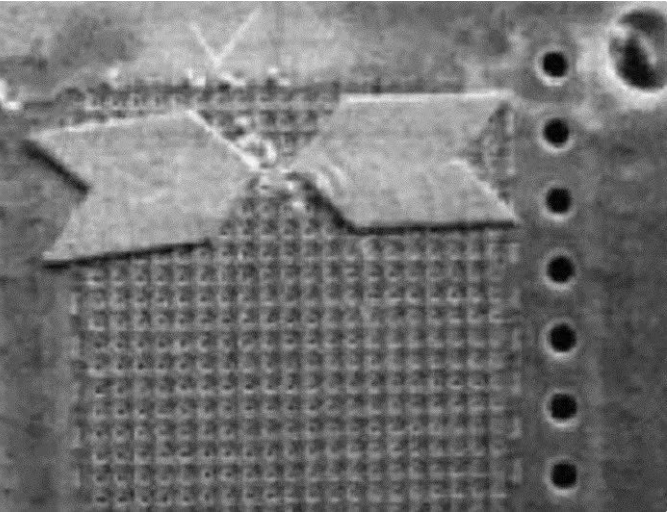
The short circuit caused by CAF failure is usually very small, so confirming the failure point is crucial to improving the success rate of CAF failure analysis. The half-point method is usually used to lock the failure area.
The importance of slice inspection
After finding the failure location, the failed product needs to be sectioned to confirm the real cause of CAF formation. By vertically grinding the failure area, the number of layers where CAF occurs can be found. When the slice is ground to the center of the hole, the path and copper migration phenomenon in the glass yarn bundle between the two holes can be observed.
Application of SEM&EDS analysis
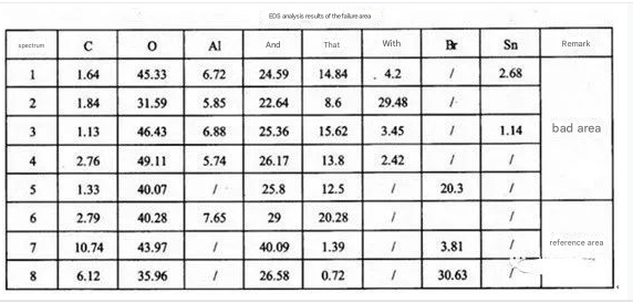
SEM&EDS analysis irradiates the sample surface with a focused electron beam, detects secondary electrons or backscattered electron information for morphological observation, and measures the wavelength and intensity of characteristic X-rays generated by the interaction between electrons and samples, and conducts qualitative or quantitative analysis of the elements contained in the tiny area. Jinjian Laboratory uses SEM to observe the appearance of the failed area of the sliced slice, and uses EDS to perform elemental analysis on the bad area, which can reveal the details of the CAF phenomenon and provide customers with scientific solutions.