Circuit Simulation and PCB Design Software
Circuit simulation software and PCB design software play complementary roles in the PCB design process, providing engineers with tools to design, simulate, verify and optimize electronic circuits.
Effective simulation analysis helps reduce the number of design, manufacturing and test iterations required for development, ensuring that circuit designs meet performance and operating goals before board manufacturing.
PSpice simulation tools and OrCAD X PCB design software are two components of the Cadence tool suite for designing and simulating electronic circuits and PCBs.
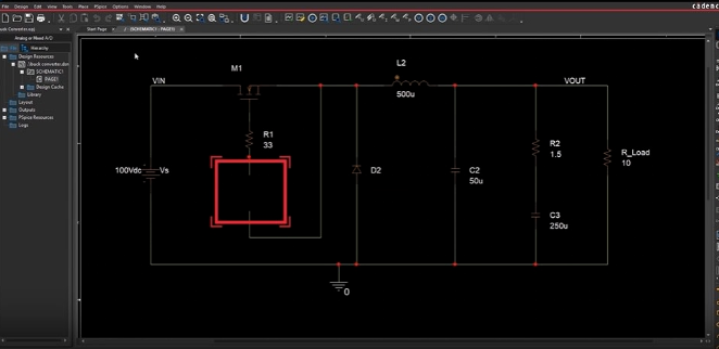
PSpice circuit simulation tool for OrCADXCapture
In the design process, the advantages of simulation are well known. Before developing and manufacturing circuit boards, using the right circuit simulation and PCB design software can timely evaluate and improve designs, thereby saving time and cost, thereby reducing design cycles and improving circuit board design efficiency. The following shows the complementary relationship between design and simulation.
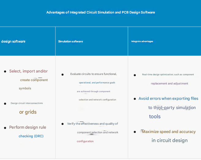
The table above highlights the relationship between IC simulation and PCB design software. Many PCB design software require designers to use third-party tools for simulation. However, exporting projects for simulation can lead to extended design and redesign time, unnecessary manufacturing costs, and reduced product development return. Cadence’s IC simulation and PCB design software can avoid these situations.
1.Cadence’s Circuit Simulation and PCB Design Software
PSpice simulation tool and OrCAD X PCB design software are two components of the Cadence electronic circuit design and simulation tool suite. Here is an overview of each tool and how they interact with each other.
2 PSpice Simulation Tool
PSpice is a powerful circuit simulation tool that allows engineers to simulate the behavior of electronic circuits before prototyping or production, allowing for thorough analysis and optimization.
3 PSpice’s key features include:
Analog and digital simulation: Supports simulation of analog, digital, and mixed-signal circuits, including components such as resistors, capacitors, inductors, transistors, operational amplifiers, digital logic gates, power electronics, and digital, analog, and power management ICs.
Circuit optimization: Use advanced analytical simulation engines in conjunction with core PSpice simulation to maximize design performance, yield, cost-effectiveness, and reliability.
Mechatronic simulation: Perform system-level simulations with support from PSpice and MathWork’s Simulink.
Behavioral modeling: Allows users to create custom models for components and subcircuits, enabling accurate representation of real-world behavior.
Reliability analysis: Smoke testing, which evaluates the thermal characteristics of components or subcircuits to verify and/or establish temperature limits for component and board operation.
Monte Carlo analysis: Facilitates statistical analysis of circuit performance by simulating multiple iterations with different component values to evaluate tolerances and sensitivities.
Sensitivity analysis: Determines the impact of component changes on circuit performance, aiding in design optimization.
04 OrCADXPCB Design Software
OrCAD X is a comprehensive PCB design solution that provides a complete set of tools for schematic design, PCB layout and simulation. It allows engineers to easily create complex PCB designs, including components, connectors, traces and layers.
05 The main features of OrCAD X include:
Schematic Design: Allows engineers to create electronic schematics using component and symbol libraries. Schematics are the blueprints for PCB layout.
Design Analysis: Provides real-time feedback on simulation results, without format conversion or file import/export, which prolongs design time and increases the chance of errors.
PCB Layout and Routing: Enables users to design the physical layout of the PCB, place components and route traces while adhering to design rules and constraints.
Design Rule Check (DRC): Ensures that the PCB design meets the specified constraints and manufacturing requirements.
3D Visualization: Provides a 3D view of the PCB design to facilitate design verification and collaboration.
Integration with DFM/DFA: Supports the export of design files in standard formats for DFM manufacturability review and DFA assembly review.
06 PSpice and OrCAD X Interaction
PSpice and OrCAD X Capture are tightly integrated, allowing seamless transfer of design data between schematic design and simulation environments. Engineers can design circuits in the OrCAD X schematic editor and simulate the circuits directly with PSpice without manually translating or converting design files. Once the circuit is simulated in PSpice, engineers can analyze the results in OrCAD X and make design modifications as needed, maintaining a synchronized workflow between design and simulation. Any changes to the schematic in OrCAD X are automatically reflected in the PSpice simulation, ensuring consistency throughout the design process. This integration simplifies the design and simulation workflow, allowing engineers to iterate quickly and efficiently to achieve the best PCB design.
Summary
Cadence PCB design software supports circuit simulation With industry-leading Cadence PCB design and analysis tools such as PSpice and OrCAD X, you get a seamless integration solution between circuit simulation and PCB design software to help you optimize your PCB development process. If you need, please contact us