Arduino-based Theo Jansen-style Octopus Robot by 3D Printing
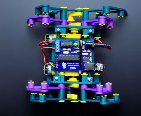
Hi everyone! In this project, I will show you an amazing eight-legged robot in the style of an octopus! It is made entirely of 3d printed parts and moves with a cool mechanism inspired by the Jansen mechanism. Two simple DC motors power the legs, making them move in a smooth and balanced manner. A simple infrared sensor circuit and controller are used to control the robot. I will start the project step by step by assembling the 3D blocks, like a puzzle, so let’s get started!
Step 1: 3D Parts and Hardware

- The project consists of a total of 79 3D parts, but don’t be scared, the main parts total 55 pieces and are about 3mm thick. The remaining 24 pieces are clamp washers 3D parts. I used Bamboo Lab A1 for standard printing, which is medium quality, and the printing time for all the parts was about 6 hours.
- I avoided using a single color when printing the parts, my purpose was to make sure that you can easily distinguish the joints and the main parts when assembling.
- At first I printed it in one color and finished the assembly, then I realized that it would be hard for the audience or reader to distinguish the parts, so I hope that different colors of parts will make it easier for you when assembling.
- During the assembly of the 3D parts, 2 simple DC gear motors were used as hardware, which are usually sold as a set of wheels and are very popular among makers. Technically, it usually runs in the range of 5 to 6 volts and the speed is about 200 to 255 RPM.
In addition, a total of 18 bolts and 4 nuts were used during the assembly process. The sizes are as follows:
- 8 M3 12MM bolts (base, top, side)
- 4 M3 25MM bolts (for DC motors)
- 4 M3 nuts (for DC motors)
- 2 M3 20MM bolts (for shaft drive)
- 2 M3 16MM bolts (for shaft drive)
- 2 M2 12MM bolts (for shaft-mtr)

Step 2: Assemble the chassis
In this section, we will first assemble the chassis. First, fix the left and right side models to the base model using M3 12MM bolts. However, without fully tightening the bolts on either side, place the upper model and complete the assembly by tightening all the bolts.
Step 3: Install the DC Gear Motor
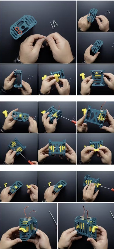
In this section, we will install the DC gear motor. First, insert 4 M3 25MM bolts at the bolt inputs on the left and right sides. Then place the model named Ax-mtr. Still on the DC motor shaft. Mount the DC motor to the M3 25MM bolts that come with the chassis and tighten them using M3 nuts. Insert the shaft component with the long shaft in the model file containing the shaft transmission component. Go to the motor (ax-mtr model) and tighten it with M2 12MM screws. Now we can proceed to the leg assembly.
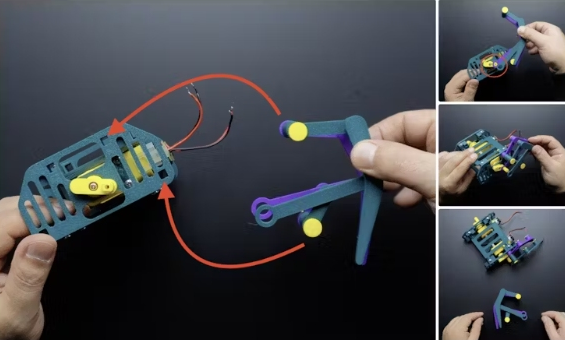
Step 4: Connect the Legs
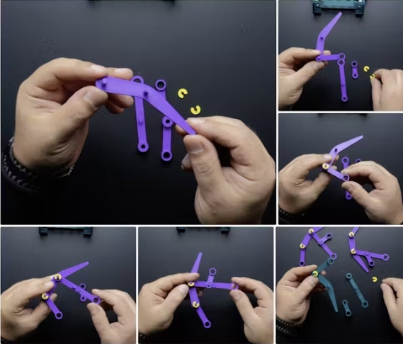
This part requires a total of 8 Leg (Leg .stl) components, 4 on each side. To connect the first leg (i.e. the purple ones in the picture, the first to be connected to the motor), connect the model called inks_1. Use STL. These have a shorter shaft. Insert the connection part into the leg part as shown in the picture and use the clamp washers. STL to secure them.
Next is the joint model inks_2. STL for connecting the second leg (that is the ink green part in the image, the part that will overlap the purple leg). These have a longer shaft. Insert the connection part into the leg as shown in the picture and use the clamp washers. STL to secure the clamps.
Finally, after the connection part, we have a total of 8 legs, now place the purple legs (the ones that are closer to the motor and have the shorter shaft) at the bottom and the dark green legs (the ones with the longer shaft) at the top (so that they overlap). Then place the longer main axle. STL model above the shaft hole and the shorter main axle. STL model below the well hole. The legs are now ready to be inserted into the chassis! In the next step, we will assemble the leg chassis.
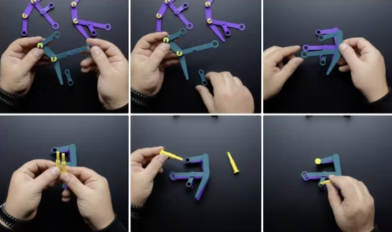
Step 5: Place and Assemble the Legs on the Chassis
In fact, it might be a bit complicated to explain this section in written form, so I added marks in some of the shared images to make it easier.
On both sides of the chassis, there are two square mounting holes for the shaft-main. STL parts that we attached to the legs earlier. Insert the main shaft. STL parts into these holes as shown and insert the legs into the chassis. At the same time, you should insert the part with the circular hole from the ink. STL part to the motor shaft. The part with the circular hole in the ink-green leg should remain free in this position to be inserted in a later step. Then insert the second leg into the chassis in the same way.
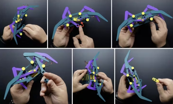
After attaching the purple part (inks_1.stl) to the motor shaft, insert the circular shaft separator part into the shaft driver. STL into the motor shaft with the purple part at the bottom. Place the stub shaft part from the model file containing the shaft driver part. Still on the motor shaft that was fixed earlier, secure it with the M3 20MM bolts.
Now place the leg part with the circular hole in the ink-green leg onto the stub shaft, then place the circular washer with the center hole onto the shaft driver and secure it with the M3 16MM bolts. STL model file.
Finally, attach the clip washer. STL parts to both ends of the axis main. STL parts for the top and bottom of the chassis. At this point, the 3D parts of the robot are assembled!
Step 6. Circuit
Now that the 3D parts of the robot are complete, we can take a look at the circuit. Actually, you can create the circuit with an Arduino board and a motor driver shield, but in this project, I will use a 2-in-1 board of my own design. I have used this board in previous projects and my followers really appreciated it.
So I made some updates and shared the final version on the PCBWay project page. The board is simple in design but very efficient, it combines a motor driver and a microcontroller to make projects involving motors easy. When designing the PCB prototype, I took care to choose components that are easy to find and solderable.
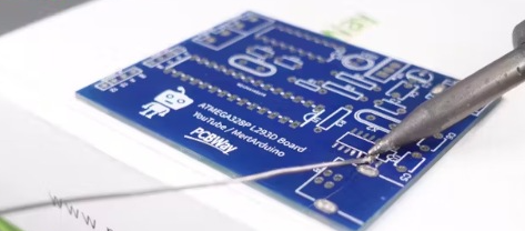
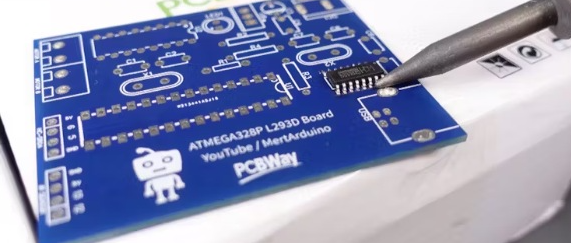
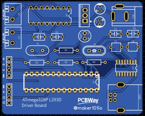
The board basically consists of three main components, an ATmega328P, an L293D motor driver, and I used a CH341 chip for easy programming via USB. Only, the CH341 USB chip seems a little difficult to solder. But using a simple soldering iron, apply a small amount of solder on the pads on the PCB where the chip will be mounted, then align the chip legs correctly and finish the soldering with the soldering iron. If you have no experience in soldering, you can use PCBWay’s assembled board service and they will send you a ready-to-use board.
In these pictures, I have shared a picture of the Bill of Materials and a picture of the Designator showing the location of the components.
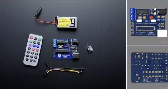
The circuit is wirelessly controlled using an IR remote controller and receiver. The IR remote controller and receiver is a very practical and simple product for robotics and hobby DIY applications. It is usually sold in a 2-in-1 kit.
Usually the kit includes:
- Remote controller (approx. 21 buttons)
- 38khz 1838B IR receiver module
- Jumper cables
In addition, a 3S 7.4 volt Li-ion battery was selected to power the circuit. Just connect the motor and IR sensor to the circuit as follows, and then insert the board and battery into the robot.
- Motor A1 = Digital 2
- Motor A2 = Digital 4
- Motor B1 = Digital 11
- Motor B2 = Digital 10
- IR Pin = Digital 12
Now that the mechanism and circuit of the robot are complete, it is time to program it!
Step 7: Source Code
Before moving to the main source code, we need to find out which commands the buttons on the remote control send, i.e. HEX values. Download the IR Remote Command Finder code that I have shared in the attachment and open it with Arduino IDE.
In this code and the main code, we have used an IR library, first we need to install the IR library and make sure you have installed the 2.6.0 version of the library. But as you can see in the image, you can easily install the library by searching for IRremote using the Arduino IDE library tool.
Then define the pins to which the IR receiver is connected and upload the code to the board. Then open the serial monitor and press the button that you will use on the remote control and you will see the commands for the buttons on the screen. Remember to write down these commands as they will be used in the next step.
If you have received the commands from the controller, then we can move to the main code (Motor_Control_IR_Code). Download the code, open it with Arduino IDE and make the following changes:
- Update the pins to which the motor is connected
- Update the pins to which the IR receiver sensor is connected
- Update the HEX value received from the remote control
- The loop() function processes the commands received from the infrared (IR) remote control and controls the motor accordingly.
- IR signal detection: Reads and processes commands from the IR sensor.
- Avoid duplicate commands: If the same command is received continuously, it is ignored and only new commands are processed.
- Command matching and motor control: Matches the received command with the predefined HEX value and performs the corresponding motor function:
- FWRD: The motor moves forward
- BKWD: The motor moves backward
- LEFT: The motor turns left
- RIGHT: The motor turns right
- STOP: The motor stops
- IR receiver reset: The IR receiver is reset to be ready for the next signal.
- Error handling and timing: When the sensor is busy, a small delay is applied to ensure stable operation.
If everything is ready, upload the code to the board, if you are using the PCB I designed you need to select the board as Arduino UNO.


