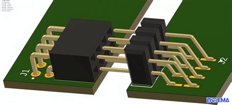
ceramic pcb soldering
Techniques For Soldering Ceramic PCBs
ceramic PCB Soldering can be a bit of a challenge, but with the right techniques, it’s totally doable. Ceramic PCBs, known for their excellent thermal conductivity and electrical insulation, are increasingly popular in high-power and high-frequency applications. However, their unique properties also mean that traditional soldering methods might not always work. So, let’s dive into some effective techniques for soldering ceramic PCBs.
First off, it’s crucial to understand that ceramic PCBs are more brittle than their fiberglass counterparts.
This means you need to handle them with extra care to avoid cracks or breaks. One of the most important steps in soldering ceramic PCBs is to ensure that the surfaces are clean. Any dirt, grease, or oxidation can prevent the solder from adhering properly. A quick wipe with isopropyl alcohol usually does the trick.
Next, let’s talk about flux.
Flux is your best friend when it comes to soldering, as it helps to clean the surfaces and improve the flow of the solder. For ceramic PCBs, a no-clean flux is often recommended because it leaves minimal residue. Apply a small amount of flux to the areas you plan to solder, and you’re good to go.
When it comes to choosing the right solder, lead-free solder is generally preferred for ceramic PCBs.
Lead-free solder has a higher melting point, which is beneficial because ceramic materials can withstand higher temperatures. However, this also means you’ll need a soldering iron that can reach these higher temperatures. A temperature-controlled soldering iron is ideal, as it allows you to set and maintain the precise temperature needed.
Now, let’s get into the actual soldering process.
Preheating the ceramic PCB can make a world of difference. Preheating helps to reduce thermal shock and ensures a more even distribution of heat. You can use a preheating plate or an oven set to a low temperature. Just be sure not to overheat the board, as this can cause damage.
Once your PCB is preheated, it’s time to start soldering.
Use a fine-tipped soldering iron for better control and precision. Touch the tip of the iron to the pad and the component lead simultaneously, then introduce the solder. The solder should flow smoothly and create a shiny, concave fillet. If the solder forms a ball or doesn’t adhere well, you might need to clean the surfaces again or adjust your temperature settings.
After you’ve finished soldering, it’s a good idea to inspect your work.
Look for any cold joints, which appear dull and grainy, as these can lead to poor electrical connections. If you spot any, reheat the joint and add a bit more solder. Also, check for any solder bridges that might create short circuits. These can be removed with a bit of desoldering braid or a solder sucker.
Finally, let your ceramic PCB cool down gradually.
Rapid cooling can cause thermal stress and potentially damage the board. Once it’s cool, give it a final inspection to ensure everything is in order.
Soldering ceramic PCBs might seem daunting at first, but with a bit of practice and the right techniques, you’ll be able to achieve reliable and high-quality solder joints. So, grab your soldering iron, take your time, and happy soldering!

Advantages Of Using Ceramic PCBs In High-Frequency Applications
When it comes to high-frequency applications, the choice of materials can make a world of difference. One material that’s been gaining traction in the tech world is ceramic, particularly in the form of ceramic PCBs. You might be wondering, why ceramic? Well, let’s dive into the advantages of using ceramic PCBs in high-frequency applications and see why they’re becoming the go-to option for many engineers and tech enthusiasts.
First off, ceramic PCBs are known for their excellent thermal conductivity.
In high-frequency applications, managing heat is crucial. Traditional materials like FR4 can struggle to dissipate heat efficiently, leading to potential overheating and failure of components. Ceramic, on the other hand, excels at spreading heat evenly across the board. This means your components stay cooler, perform better, and have a longer lifespan. It’s like giving your high-frequency circuits a breath of fresh air.
Moreover, ceramic PCBs offer superior electrical insulation.
High-frequency signals can be quite finicky, and any interference can lead to signal degradation or loss. Ceramic materials provide a stable and reliable platform that minimizes electrical interference. This ensures that your signals remain clean and intact, which is essential for applications like RF communication, radar systems, and advanced computing. It’s like having a clear, static-free conversation on a high-quality phone line.
Another significant advantage is the mechanical strength of ceramic PCBs.
High-frequency applications often involve complex and delicate components that need a sturdy foundation. Ceramic boards are incredibly robust and can withstand physical stress and environmental factors better than their traditional counterparts. This durability translates to fewer failures and less maintenance, saving both time and money in the long run. Imagine having a rock-solid foundation for your high-tech skyscraper; that’s what ceramic PCBs offer.
In addition to their strength, ceramic PCBs are also highly resistant to chemical corrosion.
In many high-frequency applications, the environment can be harsh, with exposure to chemicals, moisture, and other potentially damaging elements. Ceramic materials are naturally resistant to these factors, ensuring that your PCB remains functional and reliable even in less-than-ideal conditions. It’s like having a superhero shield protecting your sensitive electronics.
Furthermore, ceramic PCBs are incredibly versatile when it comes to design.
They can be manufactured in various shapes and sizes, allowing for greater flexibility in your projects. This adaptability is particularly beneficial in high-frequency applications where space and layout can be critical. Whether you need a compact design for a small device or a larger board for more complex systems, ceramic PCBs can be tailored to meet your specific needs. It’s like having a custom-made suit that fits perfectly, no matter the occasion.
Lastly, let’s not forget about the environmental benefits.
Ceramic materials are generally more eco-friendly compared to traditional PCB materials. They are often made from natural, abundant resources and can be recycled more easily. In an age where sustainability is becoming increasingly important, choosing ceramic PCBs can be a step towards greener technology. It’s like driving a hybrid car; you get the performance you need while also doing your part for the planet.
In conclusion, the advantages of using ceramic PCBs in high-frequency applications are numerous and compelling. From superior thermal management and electrical insulation to mechanical strength and chemical resistance, ceramic PCBs offer a robust and reliable solution for modern technology. Add in their design versatility and environmental benefits, and it’s clear why they’re becoming a popular choice. So, the next time you’re working on a high-frequency project, consider giving ceramic PCBs a try. You might just find that they’re the perfect fit for your needs.
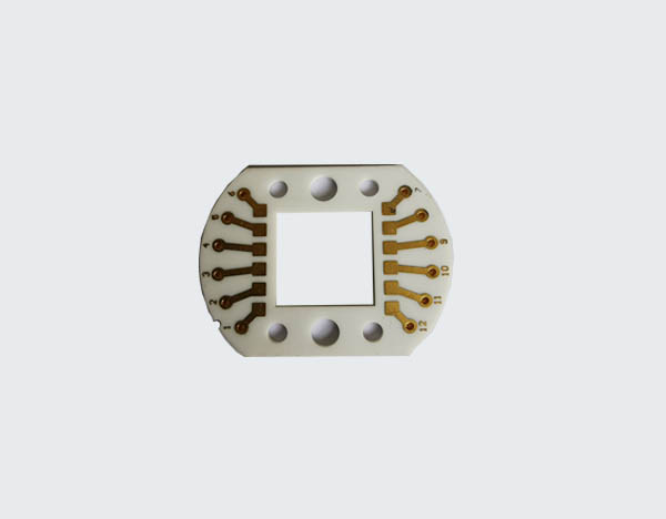
Common Challenges In Ceramic PCB Soldering And How To Overcome Them
Ceramic PCB soldering can be a bit of a tricky business, even for those who have been in the electronics game for a while. The unique properties of ceramic materials, while offering some fantastic benefits like excellent thermal conductivity and high-temperature resistance, also present a set of challenges that can make the soldering process a bit more complex. But don’t worry, with a little know-how and some practical tips, you can overcome these hurdles and achieve a solid, reliable solder joint.
One of the first challenges you might encounter is the high thermal conductivity of ceramic substrates.
This property, while great for heat dissipation, means that the ceramic can quickly draw heat away from the soldering area. As a result, achieving the right temperature for soldering can be difficult. To tackle this, you might want to use a soldering iron with a higher wattage or a hot air rework station. These tools can provide the necessary heat to ensure that the solder flows properly and forms a good bond with the ceramic surface.
Another common issue is the potential for thermal shock.
Ceramic materials can be quite brittle, and rapid temperature changes can cause them to crack. To avoid this, it’s crucial to preheat the ceramic PCB before you start soldering. Gradually increasing the temperature of the board can help to minimize the risk of thermal shock and ensure that the ceramic remains intact throughout the process. Additionally, using a controlled cooling process after soldering can further reduce the chances of cracking.
Flux application is another area where you might run into some difficulties.
Ceramic surfaces are typically non-metallic and non-conductive, which can make it harder for the flux to adhere properly. Without adequate flux, the solder may not wet the surface effectively, leading to poor joint formation. To overcome this, you can use a specialized flux designed for ceramic materials. These fluxes are formulated to work better with non-metallic surfaces, improving the wetting action and helping to create a stronger bond.
Moreover, the choice of solder can also play a significant role in the success of your soldering efforts.
Traditional lead-based solders might not always be the best choice for ceramic PCBs, especially if you’re working in an environment where lead-free processes are required. Lead-free solders, such as those based on tin-silver-copper (SAC) alloys, can provide better performance on ceramic substrates. These solders typically have higher melting points, which can be advantageous given the high thermal conductivity of ceramic materials.
In addition to these technical challenges, handling and positioning components on a ceramic PCB can also be a bit more demanding.
Ceramic boards are often more fragile than their fiberglass counterparts, so it’s important to handle them with care to avoid any accidental damage. Using precision tools and techniques, such as tweezers and magnifying glasses, can help you place components accurately without putting undue stress on the board.
Finally, it’s worth mentioning that practice makes perfect. The more you work with ceramic PCBs, the more familiar you’ll become with their quirks and characteristics. Over time, you’ll develop a better sense of how to manage heat, apply flux, and choose the right solder for the job. So, don’t get discouraged if your first few attempts don’t go as smoothly as you’d like. With patience and persistence, you’ll soon be soldering ceramic PCBs like a pro.
In conclusion, while ceramic PCB soldering does come with its own set of challenges, they are by no means insurmountable. By understanding the unique properties of ceramic materials and employing the right techniques and tools, you can overcome these obstacles and achieve reliable, high-quality solder joints. Happy soldering!

Best Practices For Ensuring Reliable Solder Joints On Ceramic PCBs
When it comes to ceramic PCB soldering, ensuring reliable solder joints is crucial for the longevity and performance of your electronic devices. Ceramic PCBs, known for their excellent thermal conductivity and mechanical stability, are increasingly popular in high-power and high-frequency applications. However, soldering on ceramic substrates can be a bit tricky due to their unique properties. To help you navigate this process, here are some best practices to ensure your solder joints are as reliable as possible.
First and foremost, it’s essential to choose the right solder paste.
Not all solder pastes are created equal, and the type you select can significantly impact the quality of your solder joints. For ceramic PCBs, a lead-free solder paste with a low melting point is often recommended. This type of solder paste reduces the risk of thermal stress on the ceramic material, which can lead to cracks or other damage. Additionally, make sure the solder paste you choose has good wetting properties to ensure it flows smoothly and creates a strong bond.
Next, let’s talk about the importance of a clean surface.
Any contaminants on the ceramic PCB can prevent the solder from adhering properly, leading to weak joints. Before you begin soldering, thoroughly clean the PCB with isopropyl alcohol to remove any dust, oils, or other residues. This simple step can make a world of difference in the quality of your solder joints.
Temperature control is another critical factor in ceramic PCB soldering.
Ceramic materials can be sensitive to rapid temperature changes, so it’s essential to use a controlled heating process. Preheating the PCB gradually can help minimize thermal shock and reduce the risk of cracking. When it comes to the actual soldering, using a reflow oven with precise temperature control is ideal. This allows you to maintain a consistent temperature throughout the process, ensuring that the solder melts and flows evenly.
In addition to temperature control, the soldering environment itself plays a role in the reliability of your joints.
Working in a controlled environment with minimal airflow can help prevent oxidation and other issues that can compromise the quality of your solder joints. If possible, use a nitrogen atmosphere during the reflow process to further reduce oxidation and improve the overall quality of your solder joints.
Another best practice is to use the right amount of solder paste.
Too much solder can lead to bridging and other defects, while too little can result in weak joints. Using a stencil to apply the solder paste can help ensure you get the right amount every time. Additionally, make sure the stencil is properly aligned with the PCB to avoid any misalignment issues.
Finally, inspection and testing are crucial steps in ensuring the reliability of your solder joints.
After soldering, carefully inspect each joint for any signs of defects, such as voids, cracks, or insufficient wetting. Using tools like X-ray inspection can help you identify hidden defects that may not be visible to the naked eye. Once you’ve inspected the joints, perform electrical testing to ensure that each connection is functioning correctly.
By following these best practices, you can significantly improve the reliability of your solder joints on ceramic PCBs. From choosing the right solder paste to maintaining a controlled environment and performing thorough inspections, each step plays a vital role in achieving high-quality, reliable solder joints. So, the next time you’re working with ceramic PCBs, keep these tips in mind to ensure your projects are a success.

