Ceramic pcb soldering
Advantages Of Using Ceramic PCBs In High-Temperature Applications
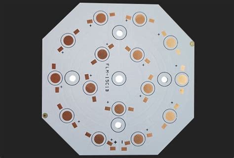
Ceramic printed circuit boards (PCBs) have emerged as a pivotal component in high-temperature applications, offering a range of advantages that make them indispensable in various industries. As technology continues to advance, the demand for materials that can withstand extreme conditions without compromising performance has become increasingly critical. Ceramic PCBs, with their unique properties, address this need effectively, providing a reliable solution for applications where traditional materials might falter.
One of the primary advantages of ceramic PCBs in high-temperature environments is their exceptional thermal conductivity.
Unlike conventional PCBs, which often rely on materials like FR-4, ceramic substrates such as aluminum oxide (Al2O3) and aluminum nitride (AlN) offer superior heat dissipation capabilities. This characteristic is crucial in applications where excessive heat can lead to component failure or reduced efficiency. By efficiently managing heat, ceramic PCBs help maintain the integrity and performance of electronic components, thereby extending their lifespan and ensuring consistent operation.
In addition to their thermal properties, ceramic PCBs exhibit remarkable mechanical strength and stability.
This robustness is particularly beneficial in high-temperature settings where materials are subjected to thermal expansion and contraction. Ceramic substrates are less prone to warping or deformation under such conditions, providing a stable platform for electronic components. This stability is essential in industries such as aerospace, automotive, and power electronics, where reliability and precision are paramount.
Moreover, ceramic PCBs offer excellent electrical insulation, which is vital for maintaining the safety and functionality of electronic systems.
The inherent insulating properties of ceramic materials prevent electrical leakage and short circuits, even at elevated temperatures. This feature is especially important in high-power applications, where electrical integrity is crucial to prevent malfunctions and ensure the safety of both the equipment and its operators.
Furthermore, the chemical resistance of ceramic PCBs adds another layer of advantage in harsh environments.
These substrates are resistant to corrosion and chemical degradation, making them suitable for use in industries where exposure to aggressive chemicals is common. This resistance ensures that the PCBs maintain their performance and reliability over time, reducing the need for frequent replacements and maintenance.
Transitioning to the aspect of miniaturization, ceramic PCBs also support the trend towards smaller, more compact electronic devices.
Their ability to integrate multiple layers and components within a limited space without compromising performance is a significant advantage. This capability is particularly relevant in the development of advanced technologies such as sensors, medical devices, and telecommunications equipment, where space constraints are a constant challenge.
In conclusion, the advantages of using ceramic PCBs in high-temperature applications are manifold.
Their superior thermal conductivity, mechanical strength, electrical insulation, chemical resistance, and support for miniaturization make them an ideal choice for industries that demand high performance and reliability under extreme conditions. As technology continues to evolve, the role of ceramic PCBs in enabling innovation and ensuring the longevity of electronic systems will undoubtedly become even more pronounced. By addressing the challenges posed by high-temperature environments, ceramic PCBs not only enhance the performance of electronic devices but also contribute to the advancement of various technological fields.
Step-By-Step Guide To Soldering On Ceramic PCBs
Soldering on ceramic PCBs, or printed circuit boards, is a specialized process that requires precision and attention to detail. Ceramic PCBs are known for their excellent thermal conductivity and electrical insulation properties, making them ideal for high-power applications. However, their unique material composition demands a careful approach to soldering. This step-by-step guide aims to provide a comprehensive understanding of the soldering process on ceramic PCBs, ensuring a successful and reliable connection.
To begin with, it is essential to gather the necessary tools and materials.
These include a high-quality soldering iron with adjustable temperature control, lead-free solder, flux, tweezers, and a magnifying glass or microscope for detailed inspection. Additionally, it is crucial to work in a well-ventilated area to avoid inhaling any fumes generated during the soldering process. Once the workspace is prepared, the next step involves cleaning the ceramic PCB. This is a critical step as any contaminants on the board can hinder the soldering process. Use isopropyl alcohol and a lint-free cloth to gently clean the surface, ensuring that all dust, oils, and residues are removed.
Following the cleaning process, the next step is to apply flux to the areas where soldering will occur.
Flux is a chemical agent that helps to clean and prepare the metal surfaces, promoting better adhesion of the solder. It is important to apply the flux sparingly, as excessive amounts can lead to unwanted residue on the board. With the flux applied, the soldering iron should be preheated to the appropriate temperature. Ceramic PCBs can withstand higher temperatures than traditional fiberglass boards, but it is still important to avoid overheating, which can damage the components or the board itself. A temperature range of 350°C to 400°C is generally recommended for ceramic PCBs.
Once the soldering iron is heated, it is time to begin the soldering process.
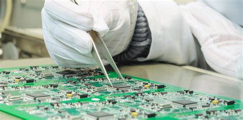
Carefully position the component on the ceramic PCB using tweezers, ensuring that it is aligned correctly with the pads. Gently press the component down to maintain contact with the board. Next, bring the soldering iron tip into contact with both the component lead and the pad on the PCB. This ensures that both surfaces are heated simultaneously, allowing the solder to flow evenly. Introduce the solder wire to the joint, allowing it to melt and form a secure connection. It is important to use just enough solder to cover the joint without creating a bulky or uneven surface.
After completing the soldering, it is crucial to inspect the joints for quality.
Use a magnifying glass or microscope to check for any cold solder joints, which appear dull and may not provide a reliable connection. If any defects are found, reheat the joint and apply additional solder as needed. Finally, clean the board once more to remove any residual flux, which can be corrosive over time. This can be done using isopropyl alcohol and a brush, ensuring that all areas are thoroughly cleaned.
In conclusion, soldering on ceramic PCBs requires careful preparation and execution. By following these steps, one can achieve a reliable and durable connection, taking full advantage of the superior properties that ceramic PCBs offer. With practice and attention to detail, soldering on ceramic PCBs can become a straightforward and rewarding process.
Common Mistakes To Avoid When Soldering Ceramic PCBs
Soldering ceramic PCBs, or printed circuit boards, is a task that requires precision and attention to detail. These boards are known for their excellent thermal conductivity and electrical insulation properties, making them ideal for high-power applications. However, the unique characteristics of ceramic materials can present challenges during the soldering process. Understanding common mistakes and how to avoid them is crucial for ensuring the reliability and performance of the final product.
One frequent mistake is the improper selection of soldering materials.
Ceramic PCBs often require specific types of solder and flux to accommodate their thermal properties. Using a solder with an inappropriate melting point can lead to insufficient bonding or damage to the board. Therefore, it is essential to choose a solder that matches the thermal expansion characteristics of the ceramic material. Additionally, selecting the right flux is crucial, as it helps remove oxides and promotes better wetting of the solder. Failing to use the correct flux can result in poor solder joints and increased resistance.
Another common error is inadequate temperature control during the soldering process.
Ceramic PCBs can withstand high temperatures, but excessive heat can still cause damage or warping. It is vital to maintain a consistent temperature that is sufficient to melt the solder without overheating the board. Utilizing a temperature-controlled soldering iron or reflow oven can help achieve this balance. Moreover, preheating the ceramic PCB before soldering can reduce thermal shock and improve solder flow, leading to more reliable connections.
In addition to temperature control, the duration of heat application is equally important.
Applying heat for too long can degrade the ceramic material or cause the solder to spread excessively, leading to bridging between adjacent pads. Conversely, insufficient heat application may result in cold solder joints, which are prone to failure. To avoid these issues, it is advisable to follow the recommended soldering profiles provided by the PCB manufacturer, which outline the optimal temperature and time settings for the specific ceramic material used.
Furthermore, improper handling of ceramic PCBs can lead to physical damage and compromised performance.
These boards are more brittle than their fiberglass counterparts, making them susceptible to cracking or chipping if mishandled. It is crucial to handle ceramic PCBs with care, using appropriate tools and techniques to avoid applying excessive force. Additionally, ensuring a clean work environment free of contaminants can prevent foreign particles from interfering with the soldering process and affecting the integrity of the solder joints.
Lastly, neglecting to perform thorough inspections and testing after soldering can result in undetected defects that compromise the functionality of the PCB.
Visual inspections should be conducted to identify any visible issues such as solder bridges, insufficient solder coverage, or misaligned components. In addition, electrical testing can verify the continuity and performance of the soldered connections. Implementing a robust quality control process can help identify and rectify any issues before the PCB is deployed in its intended application.
In conclusion, soldering ceramic PCBs requires careful consideration of material selection, temperature control, handling practices, and post-soldering inspections. By avoiding common mistakes and adhering to best practices, one can ensure the production of reliable and high-performing ceramic PCBs suitable for demanding applications.
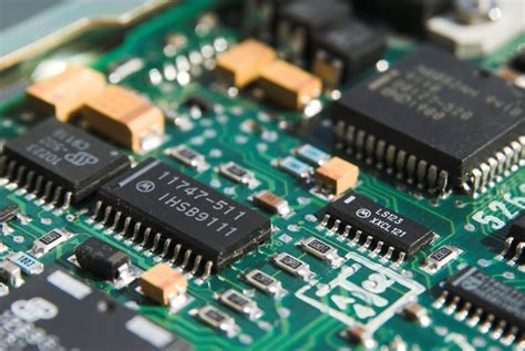
Comparing Ceramic PCBs To Traditional FR4 Boards In Soldering
Ceramic PCBs, or printed circuit boards, have gained significant attention in recent years due to their unique properties and advantages over traditional FR4 boards, particularly in the context of soldering. Understanding the differences between these two types of PCBs is crucial for engineers and manufacturers who aim to optimize their electronic designs for performance and reliability.
To begin with, ceramic PCBs are known for their excellent thermal conductivity, which is a critical factor in soldering processes.
Unlike FR4 boards, which are made from a composite material of woven fiberglass cloth with an epoxy resin binder, ceramic PCBs are composed of materials such as alumina or aluminum nitride. These materials offer superior heat dissipation, allowing for more efficient thermal management during soldering. This characteristic is particularly beneficial in high-power applications where excessive heat can lead to component failure or reduced lifespan.
Moreover, the thermal stability of ceramic PCBs provides an advantage over FR4 boards.
During soldering, the heat applied can cause expansion and contraction of the board material. Ceramic PCBs exhibit minimal thermal expansion, reducing the risk of mechanical stress and potential damage to solder joints. In contrast, FR4 boards are more susceptible to thermal expansion, which can lead to issues such as warping or delamination, ultimately compromising the integrity of the soldered connections.
In addition to thermal properties, the mechanical strength of ceramic PCBs is another factor that distinguishes them from traditional FR4 boards.
Ceramic materials are inherently more robust and resistant to mechanical stress, which is advantageous during the soldering process. This strength ensures that the board can withstand the rigors of manufacturing and assembly without suffering from cracks or other structural failures. On the other hand, FR4 boards, while generally durable, may not offer the same level of mechanical resilience, particularly in demanding environments.
Furthermore, the dielectric properties of ceramic PCBs contribute to their superiority in certain applications.
The low dielectric constant and loss tangent of ceramic materials result in reduced signal loss and improved electrical performance. This is particularly important in high-frequency applications where signal integrity is paramount. While FR4 boards are widely used and offer satisfactory performance for many applications, they may not match the electrical performance of ceramic PCBs in these specific scenarios.
Despite these advantages, it is important to acknowledge that ceramic PCBs also present certain challenges in soldering.
The cost of ceramic materials and the complexity of their manufacturing processes can be higher compared to FR4 boards. Additionally, the brittleness of ceramics requires careful handling during assembly to prevent damage. These factors must be considered when deciding between ceramic and FR4 PCBs for a particular application.
In conclusion, the choice between ceramic PCBs and traditional FR4 boards in soldering depends on various factors, including thermal management, mechanical strength, and electrical performance requirements. While ceramic PCBs offer significant advantages in terms of thermal conductivity, stability, and dielectric properties, they also come with higher costs and handling considerations. By carefully evaluating the specific needs of their applications, engineers and manufacturers can make informed decisions that optimize the performance and reliability of their electronic designs.

Essential Tools And Materials For Soldering Ceramic PCBs
Soldering ceramic printed circuit boards (PCBs) requires a precise approach and the right set of tools and materials to ensure a successful outcome. Ceramic PCBs, known for their excellent thermal conductivity and electrical insulation properties, are increasingly used in high-performance applications. Therefore, understanding the essential tools and materials for soldering these boards is crucial for achieving optimal results.
To begin with, a high-quality soldering iron is indispensable.
When working with ceramic PCBs, it is important to use a soldering iron with adjustable temperature control. This feature allows for precise temperature settings, which is critical given the thermal sensitivity of ceramic materials. A soldering iron with a fine tip is also recommended, as it provides better control and accuracy when working on small and intricate components.
In addition to the soldering iron, a reliable soldering station is necessary.
A soldering station not only provides a stable platform for the soldering iron but also often includes features such as temperature calibration and digital displays for monitoring. These features enhance the precision and efficiency of the soldering process, making it easier to maintain consistent results.
Moreover, the choice of solder is another vital consideration.
Lead-free solder is commonly used due to environmental and health concerns associated with lead-based solders. However, it is essential to select a solder with a suitable melting point and composition for ceramic PCBs. Typically, a solder with a tin-silver-copper (SAC) alloy is preferred, as it offers good mechanical strength and thermal fatigue resistance.
Flux is another critical material in the soldering process.
It serves to clean the surfaces to be joined and facilitates the flow of solder, ensuring a strong bond. For ceramic PCBs, a no-clean flux is often recommended, as it leaves minimal residue and reduces the need for post-soldering cleaning. However, it is important to ensure compatibility between the flux and the solder to prevent any adverse reactions.
Furthermore, a hot air rework station can be an invaluable tool when soldering ceramic PCBs.
This equipment allows for the precise application of heat to specific areas, which is particularly useful for reflow soldering and desoldering components. The ability to control airflow and temperature ensures that the ceramic substrate is not damaged during the process.
Additionally, a magnifying tool, such as a magnifying lamp or microscope, is essential for inspecting solder joints.
Given the small size and complexity of components on ceramic PCBs, visual inspection is crucial to identify any defects or incomplete solder joints. A magnifying tool provides the necessary magnification to perform detailed inspections and ensure the quality of the soldering work.
Finally, safety equipment should not be overlooked. Soldering involves high temperatures and potentially harmful fumes, so it is important to use safety goggles and a fume extractor. These precautions protect the eyes from accidental splashes of molten solder and ensure a safe working environment by removing harmful fumes from the air.
In conclusion, soldering ceramic PCBs requires a combination of the right tools and materials to achieve high-quality results. From a precise soldering iron and station to the appropriate solder and flux, each component plays a crucial role in the process. By understanding and utilizing these essential tools and materials, one can ensure the successful soldering of ceramic PCBs, thereby enhancing the performance and reliability of electronic devices.

