Common Methods for Mitigating Electromagnetic Interference
This article describes methods that can help reduce or even eliminate annoying EMI, resulting in a robust electronic design.
Defining EMC
Electromagnetic compatibility (EMC) is defined as the ability of electrical devices and systems to operate effectively in an electromagnetic environment.
In a system where EMC is required, components will act as electromagnetic sources and the goal is to reduce their interference. Components that are susceptible to interference will usually be hardened to reduce the problem.
When end-equipment manufacturers integrate components from different suppliers, the best way to ensure that the interference source and the susceptible circuit can coexist harmoniously is to form a set of general rules where the interference will be limited to a certain level and the susceptible circuit can fully handle that level of interference.
EMI Reduction Methods
There are many strategies that can be used to reduce EMI, including shielding, grounding, filtering, component selection, and even software tuning.
Specifically, a metal shielded enclosure can be added around the circuit that generates the EMI. In some cases, this may be easier to achieve by enclosing the entire circuit board. Depending on the source of the EMI, cables and connectors can also be shielded.
Most of the time, ground planes and ground planes on a printed circuit board (PCB) are effective at reducing EMI. Of course, proper design techniques need to be employed to avoid ground loops. Multilayer PCBs can take advantage of ground stitching, using vias to connect ground planes on different layers together.
Low-pass filters, decoupling capacitors, inductors, and ferrite beads are often used to attenuate unwanted high-frequency signals. Including these types of passive devices provides a way to eliminate the need for more expensive shielding.
Component selection and software tuning may come into play in certain applications. The former often comes down to choosing between a linear or switch-mode power supply (SMPS). The latter assumes that the software is actively involved in the power control aspects of the design, such as motor control systems or software-defined radios.
EMI: The Price of Using a Switch-Mode Power Supply
In most applications, an SMPS can radically improve the efficiency of a linear regulator, but it comes at a price. The switching of the power metal-oxide semiconductor field-effect transistor (MOSFET) is often a significant source of EMI and can negatively impact reliability. This EMI is generated by discontinuous input current, fast rising slew rates at the switch node, and increased ringing along the switching edges due to parasitic inductance in the power loop.
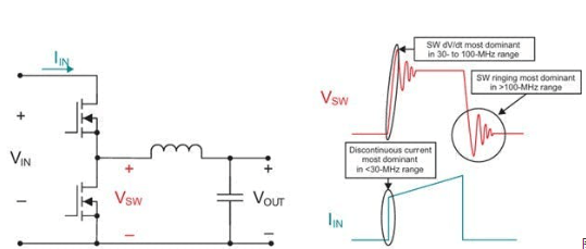
Figure 1 depicts how each of these components manifests itself in different frequency bands using a buck converter topology as an example.
Sources of EMI in a Switched Mode Power Supply Figure 1. Below are examples of EMI sources in a switched mode power supply (SMPS). 7 Solving PCB EMI Problems
There are various types of vias to choose from, such as plated through hole (PTH) vias. PTH vias are low cost and easy to manufacture. However, it has a small disadvantage, namely “stubs” (these are the parts of the via that are not in the intended signal path). Stub resonances in multilayer PCB designs can be optimized to reduce losses.
Such stubs can have an adverse effect on high-speed signal characteristics, especially when the problem leads to a significant increase in data rates and the length of the stub in thicker PCBs. The stub will act like a resonant circuit, storing the highest energy at a specific resonant frequency. If the signal has a strong component at or near this resonant frequency, it can end up causing significant signal attenuation (Figure 2).
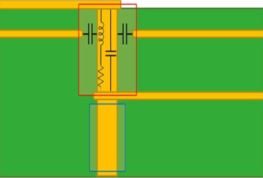
Figure 2. Via stub resonance is shown.
This resonant frequency of a via stub has a significant effect on the insertion loss of the signal, leading to EMI issues.
The solution to these problems is to adjust the stub length so that it affects the frequency at which EMI occurs. By optimizing the stub length to fit their desired frequency range, designers will be able to effectively control problematic EMI.