Essential Files Required for PCB Prototyping: A Comprehensive Guide
Printed Circuit Board (PCB) prototyping is a crucial step in electronics design and manufacturing. Before a PCB can be produced, designers must provide specific files to ensure accuracy, functionality, and manufacturability. This guide outlines the essential files needed for PCB prototyping, their purposes, and best practices for file preparation.
1. Introduction to PCB Prototyping
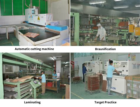
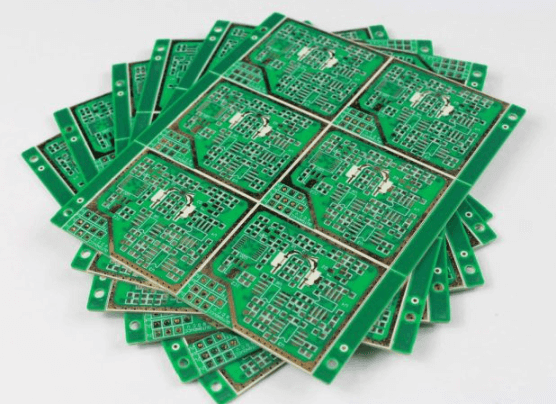
PCB prototyping involves creating a small batch of boards for testing and validation before full-scale production. To manufacture a PCB, manufacturers require a set of standardized files that define the board’s layout, components, and fabrication requirements. Providing the correct files ensures that the prototype meets design specifications and functions as intended.
2. Essential Files for PCB Prototyping
The following files are typically required for PCB fabrication and assembly:
2.1 Gerber Files
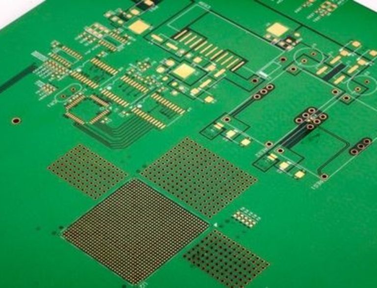
Purpose: Gerber files are the industry standard for PCB fabrication. They contain all the necessary information about the PCB’s layers, including copper traces, solder mask, silkscreen, and drill holes.
Key Gerber Files:
- Copper Layers (e.g.,
TopLayer.gbr,BottomLayer.gbr) – Define conductive traces. - Solder Mask (e.g.,
TopSolderMask.gbr,BottomSolderMask.gbr) – Indicate where solder should not be applied. - Silkscreen (e.g.,
TopSilk.gbr,BottomSilk.gbr) – Contain component labels and markings. - Drill Files (e.g.,
Drill.drlorNC Drill Files) – Specify hole locations and sizes. - Board Outline (e.g.,
Outline.gbrorMechanical.gbr) – Define the PCB’s shape and dimensions.
Best Practices:
- Use RS-274X (Extended Gerber) format for compatibility.
- Verify Gerber files using a viewer (e.g., GerberLook, KiCad GerbView).
2.2 Drill Files (Excellon Format)
Purpose: These files provide details about drilled holes (vias, through-holes) and their coordinates.
Types:
- Through-Hole Drills – For component leads.
- Vias – For layer connections.
- Plated/Non-Plated Holes – Indicate whether holes are conductive.
Best Practices:
- Ensure drill files match the Gerber layers.
- Specify plated vs. non-plated holes clearly.
2.3 Bill of Materials (BOM)
Purpose: The BOM lists all components required for PCB assembly, including part numbers, quantities, and reference designators.
BOM Contents:
- Reference Designator (e.g., R1, C2, U3)
- Component Description (e.g., “10kΩ Resistor”)
- Manufacturer Part Number (MPN)
- Quantity
- Footprint/Package (e.g., 0805, SOIC-8)
Best Practices:
- Use a spreadsheet (CSV, XLSX) for easy processing.
- Include alternate part numbers if available.
2.4 Pick-and-Place (PnP) File
Purpose: This file helps automated machines place surface-mount components accurately.
PnP File Contents:
- Reference Designator
- X/Y Coordinates (component position)
- Rotation Angle
- Layer (Top/Bottom)
Best Practices:
- Generate from PCB design software (e.g., Altium, KiCad, Eagle).
- Verify coordinates to prevent misalignment.
2.5 Schematic Diagram
Purpose: While not always mandatory, schematics help manufacturers understand circuit functionality and troubleshoot issues.
Best Practices:
- Provide in PDF format for readability.
- Ensure consistency between schematics and PCB layout.
2.6 Centroid File (Optional)
Purpose: Similar to PnP files, centroid files provide exact component placement data for automated assembly.
Best Practices:
- Include X/Y coordinates, rotation, and side (Top/Bottom).
2.7 Readme/Assembly Notes
Purpose: Additional instructions for manufacturers regarding special requirements (e.g., impedance control, finish type, testing).
Common Notes:
- PCB Thickness (e.g., 1.6mm)
- Surface Finish (e.g., HASL, ENIG, OSP)
- Impedance Requirements (for high-speed designs)
- Special Stackup Requirements (for multilayer PCBs)

3. Optional but Helpful Files
Some manufacturers may request additional files depending on complexity:
3.1 3D Model (STEP File)
Purpose: Helps visualize PCB fitment in enclosures.
Best Practices:
- Export from CAD tools (e.g., Altium, Fusion 360).
3.2 IPC-356 Netlist
Purpose: Ensures electrical connectivity matches the design.
Best Practices:
- Useful for high-reliability applications.
3.3 Fabrication Drawing (PDF/DXF)
Purpose: Provides a human-readable overview of PCB specs.
Best Practices:
- Include dimensions, layer stackup, and critical notes.
4. File Naming Conventions
To avoid confusion, use a standardized naming scheme:
- Example:
ProjectName_TopLayer.gbrProjectName_Drill.drlProjectName_BOM.csv

5. How to Verify Files Before Submission
Before sending files to a manufacturer:
- Use a Gerber Viewer (e.g., ViewMate, Gerbv) to check layer alignment.
- Cross-Check BOM and PnP Files for consistency.
- Confirm Drill File Accuracy (hole sizes and positions).
- Review Assembly Notes for special requirements.
6. Common Mistakes to Avoid
- Missing Layers (e.g., forgetting solder mask files).
- Incorrect Drill File Format (Excellon vs. non-standard).
- Unclear BOM Entries (ambiguous part numbers).
- No Readme File (leading to manufacturing errors).
7. Conclusion
Providing the correct files for PCB prototyping ensures smooth manufacturing and reduces errors. The essential files include Gerber files, drill files, BOM, PnP files, and assembly notes. By following best practices in file preparation and verification, designers can accelerate prototyping and achieve high-quality results.
For reliable PCB fabrication, always confirm file requirements with your manufacturer and double-check all submitted data. Proper file preparation saves time, cost, and ensures a successful prototype.