Exide Inverter PCB Components and Performance Guide
Key Takeaways
When working with Exide inverter PCB systems, understanding core components like MOSFETs, relays, and control cards ensures optimal performance. These elements manage power distribution, overload protection, and short-circuit prevention—critical for heavy-duty operations. To maintain reliability, prioritize PCB manufacturing companies with expertise in industrial-grade designs, as this directly impacts durability under high-stress conditions.
Tip: Always verify technical specifications (e.g., voltage ratings, thermal thresholds) when sourcing parts to avoid compatibility issues.
While PCB manufacturing cost is a consideration, cutting corners on materials like copper thickness or solder masks can compromise safety. Reputable PCB manufacturing businesses balance affordability with adherence to international standards, ensuring components withstand surges and heat fluctuations. For instance, Climax Components uses advanced ASIC technology to optimize efficiency, reducing energy loss in inverters.
If you’re troubleshooting, start by inspecting diodes and relays for wear—common failure points in aging systems. Pairing robust PCB manufacturing practices with regular maintenance (e.g., cleaning dust buildup, testing connections) extends the lifespan of critical parts. Remember: a well-designed PCB isn’t just about circuitry—it’s about integrating protection mechanisms that align with your inverter’s peak performance demands.
Exide Inverter PCB Components Breakdown
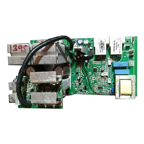
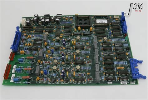
When examining an Exide inverter’s PCB manufacturing process, you’ll notice its design prioritizes precision and durability. The core components include MOSFETs (Metal-Oxide-Semiconductor Field-Effect Transistors), which regulate power flow, and high-current relays that manage load switching. These parts work alongside fast-recovery diodes to minimize energy loss during conversion. For reliable performance, PCB manufacturing companies often use multi-layered boards with heat-resistant substrates to handle thermal stress.
Here’s a breakdown of critical components:
| Component | Function | Key Specification |
|---|---|---|
| MOSFETs | Power regulation & switching | Low RDS(on), high voltage rating |
| Relays | Load management | 30-40A current capacity |
| Control Card | Signal processing & feedback | Embedded overload protection |
| Diodes | Reverse current prevention | Fast recovery time (<50ns) |
Understanding PCB manufacturing cost factors helps explain why premium materials like copper-clad laminates and ceramic capacitors are non-negotiable for heavy-duty applications. Overload protection circuits, integrated into the control card, rely on precision resistors and optocouplers to isolate faults. For businesses, partnering with trusted PCB manufacturing business providers ensures access to ASIC-driven designs that optimize efficiency.
Short-circuit prevention hinges on fuse arrays and current-limiting resistors, which safeguard sensitive traces. If you’re troubleshooting, always verify solder joints and component alignment—common failure points in poorly manufactured boards. For replacements, high-quality components ensure long-term reliability, especially in environments with fluctuating loads. By prioritizing robust PCB manufacturing standards, you extend the inverter’s operational lifespan while maintaining peak efficiency.
MOSFETs and Relays in Power Management
When managing power flow in an Exide inverter, MOSFETs (Metal-Oxide-Semiconductor Field-Effect Transistors) and relays play distinct yet complementary roles. MOSFETs act as high-speed switches, regulating current with minimal energy loss, while relays handle heavier loads by physically connecting or disconnecting circuits. Their integration into the PCB manufacturing process requires precision—poorly aligned components can lead to overheating or voltage instability.
Reputable PCB manufacturing companies prioritize thermal management in their designs, embedding heat sinks or copper layers to dissipate excess energy. This directly impacts PCB manufacturing cost, as advanced materials and multilayer designs increase durability but also production expenses. For instance, using industrial-grade MOSFETs with higher current ratings ensures reliability during power surges, but balancing performance with PCB manufacturing business budgets demands careful component selection.
Transitioning between these elements, you’ll notice that relays often include arc suppression features to prevent contact degradation—a critical factor in long-term performance. By collaborating with experienced PCB manufacturing partners, you ensure that both MOSFETs and relays are optimally placed to minimize electromagnetic interference, a common challenge in densely packed circuits. This synergy between design and execution not only enhances efficiency but also aligns with technical specifications for overload protection outlined in later sections.
Control Card Functions and Overload Protection
The control card acts as the brain of your Exide inverter, coordinating interactions between MOSFETs, relays, and sensors to maintain stable power output. By monitoring voltage fluctuations and load demands in real time, it adjusts switching frequencies to prevent overload conditions. This is achieved through current-limiting algorithms that automatically reduce power draw when thresholds exceed safe levels, protecting both the PCB manufacturing integrity and connected devices.
For optimal performance, ensure your PCB manufacturing companies use high-quality materials like flame-retardant substrates and thick copper traces. These choices directly impact heat dissipation and durability during prolonged overload scenarios. Advanced designs integrate thermal sensors that communicate with the control card, triggering shutdown protocols if temperatures rise beyond PCB manufacturing cost-effective safety margins.
When troubleshooting, check for firmware updates that refine overload response times—a critical factor in minimizing wear on PCB manufacturing business-grade components. Properly calibrated control systems not only extend inverter lifespan but also reduce energy waste by balancing efficiency with protective measures. Always verify compatibility between the control card’s logic and your inverter’s technical specifications to avoid mismatched signaling, which can lead to false overload triggers or delayed protections.
Short-Circuit Prevention Techniques Explained
When working with PCB manufacturing for inverters like Exide’s, preventing short circuits requires a combination of design precision and component selection. Start by ensuring proper trace spacing and insulation layers during PCB manufacturing business processes—this minimizes accidental contact between conductive paths. High-quality MOSFETs and fast-acting fuses act as first-line defenses, interrupting excess current before it damages the board.
Reputable PCB manufacturing companies integrate thermal relief patterns and isolation gaps around high-current components, reducing heat buildup and cross-conduction risks. For added protection, conformal coating shields the board from moisture and debris, which are common culprits of unintended conductivity. When evaluating PCB manufacturing cost, prioritize overcurrent protection circuits and self-resetting polymer fuses—these may raise initial expenses but prevent costly failures long-term.
Advanced designs use current sensors paired with control cards to instantly cut power during anomalies. Always verify that your supplier follows IPC-A-610 standards for solder joints and component placement, as even minor defects in PCB manufacturing can compromise safety. By balancing PCB manufacturing cost with robust design practices, you ensure your inverter operates reliably under heavy loads while maintaining compliance with industry safety protocols.

Technical Specifications for Reliable Performance
When evaluating PCB manufacturing for Exide inverters, understanding technical specifications ensures your system operates at peak efficiency. Key parameters like current-carrying capacity (typically 20-60A for heavy-duty models), operating voltage ranges (12V-48V DC input), and thermal resistance thresholds (≤1.5°C/W) directly impact performance stability. Reputable PCB manufacturing companies prioritize high-grade materials, such as FR-4 substrates with 2oz copper layers, to handle heat dissipation and minimize voltage drops.
For short-circuit prevention, trace widths are optimized (≥0.3mm for high-current paths) alongside arc-resistant coatings to isolate conductive elements. Overload protection relies on precision-tuned fuses (fast-acting 10kA interrupt ratings) and current-sensing resistors integrated into the control circuitry. While PCB manufacturing cost may vary with component density, investing in ISO-certified suppliers ensures compliance with IPC-A-610 standards for solder joints and component placement.
If you’re managing a PCB manufacturing business, balancing cost-efficiency with durability is critical. For instance, using automated optical inspection (AOI) during production reduces defects, while conformal coating extends lifespan in humid environments. Always verify temperature cycling test results (-40°C to +125°C) to guarantee reliability under extreme conditions—a non-negotiable for industrial-grade inverters.
Climax Components: Quality Parts Overview
When selecting components for your Exide inverter PCB, partnering with reputable pcb manufacturing companies ensures access to precision-engineered parts designed for heavy-duty performance. Climax Components specializes in pcb manufacturing processes that prioritize durability, with rigorous testing protocols for MOSFETs, relays, and control cards. Their expertise minimizes pcb manufacturing cost through optimized material selection while maintaining compliance with international safety standards.
For businesses scaling their pcb manufacturing business, Climax offers tailored solutions—from heat-resistant substrates to corrosion-proof traces—that align with the technical specifications discussed earlier. You’ll notice their components integrate seamlessly with ASIC-driven control systems, enhancing inverter efficiency without compromising overload protection features. By sourcing from certified manufacturers, you reduce risks of voltage fluctuations or thermal stress failures, directly supporting the short-circuit prevention techniques outlined in prior sections.
Whether upgrading existing systems or commissioning custom designs, prioritize suppliers who balance pcb manufacturing innovation with field-proven reliability. This approach ensures your inverter’s longevity while maintaining alignment with performance benchmarks like input/output tolerances and surge protection thresholds.
Optimizing Inverter Efficiency with ASIC Tech
When aiming to maximize your inverter’s performance, integrating ASIC (Application-Specific Integrated Circuit) technology into the PCB manufacturing process can be transformative. Unlike generic circuits, ASICs are tailored for precise power management, enabling dynamic voltage regulation and real-time thermal monitoring to minimize energy loss. Leading PCB manufacturing companies leverage these chips to reduce PCB manufacturing cost while enhancing reliability, particularly in heavy-duty applications like Exide inverters.
By embedding ASICs directly into the board design, you eliminate redundant components, streamlining signal pathways for faster response times. This precision engineering not only improves overload handling but also extends the lifespan of critical parts like MOSFETs and control cards. For businesses scaling their PCB manufacturing business, adopting ASIC-driven designs ensures consistent quality across production batches, reducing downtime and maintenance needs.
However, balancing performance gains with PCB manufacturing cost requires careful material selection. High-grade substrates and optimized trace layouts work synergistically with ASICs to dissipate heat efficiently, preventing hotspots. Partnering with certified suppliers like Climax Components guarantees access to industry-tested ASIC-integrated boards, ensuring your inverter operates at peak efficiency even under extreme loads.
As you explore advanced solutions, remember that ASIC technology isn’t just about raw power—it’s about creating smarter, more adaptable systems that evolve with your energy demands.
Maintenance Tips for Long-Term PCB Durability
To ensure your Exide inverter PCB remains reliable, adopt a proactive maintenance routine. Start by scheduling regular inspections of critical components like solder joints and traces, which degrade under thermal stress. Dust accumulation can impair heat dissipation—use compressed air or anti-static brushes to clean surfaces without damaging sensitive parts. Monitor environmental factors: excessive humidity accelerates corrosion, while temperature fluctuations weaken connections.
When cleaning, avoid abrasive chemicals that strip protective coatings. Instead, opt for isopropyl alcohol and lint-free cloths to preserve PCB manufacturing integrity. For complex repairs, partner with certified PCB manufacturing companies to source authentic replacements, as counterfeit parts often compromise performance.
Track PCB manufacturing cost trends to budget for periodic upgrades—high-quality materials from reputable suppliers reduce long-term failure risks. Implement surge protectors and stable power inputs to minimize electrical stress, extending the board’s lifespan. Finally, document maintenance activities to identify recurring issues, optimizing your PCB manufacturing business strategy for durability. This approach balances preventive care with cost efficiency, keeping your inverter running smoothly for years.
Conclusion
When maintaining or upgrading your Exide inverter’s performance, understanding the role of PCB manufacturing in ensuring reliability is critical. High-quality MOSFETs, control cards, and relays depend on precision-driven pcb manufacturing companies to deliver consistent power management and protection features. While pcb manufacturing cost may influence your sourcing decisions, prioritizing robust materials and certified suppliers ensures long-term durability, especially for heavy-duty applications.
Partnering with trusted pcb manufacturing business specialists like Climax Components guarantees access to components engineered for overload protection and short-circuit prevention. By aligning technical specifications with industry standards—such as optimal thermal management and solder integrity—you safeguard your inverter’s efficiency. Remember, the longevity of your system hinges not just on individual parts but on the synergy between advanced ASIC technology and meticulous pcb manufacturing practices. Regular maintenance, combined with professional-grade components, ensures your Exide inverter operates at peak performance for years to come.
FAQs
How do PCB manufacturing processes affect inverter reliability?
High-quality pcb manufacturing ensures proper heat dissipation and circuit integrity. Reputable pcb manufacturing companies use industrial-grade materials to handle high current loads, directly impacting your inverter’s lifespan and stability.
What factors influence pcb manufacturing cost for inverter systems?
The pcb manufacturing cost depends on layer count, copper thickness, and component density. For heavy-duty applications like inverters, opting for advanced thermal management features may increase initial costs but reduces long-term failure risks.
Can I source components separately for a custom PCB build?
While possible, mismatched parts often cause compatibility issues. Established pcb manufacturing business providers like Climax Components pre-test MOSFETs and relays to ensure seamless integration, saving you troubleshooting time.
How do I verify if a PCB meets Exide inverter specifications?
Check for certifications like UL or RoHS compliance. Reliable pcb manufacturing companies provide detailed datasheets covering voltage thresholds, temperature ranges, and surge protection ratings aligned with Exide’s technical requirements.
Why does short-circuit prevention require specialized PCB design?
Robust pcb manufacturing incorporates isolated traces, fused pathways, and overload-responsive control cards. These features minimize arc risks during voltage spikes, a critical safeguard in high-power inverters.
Need Custom PCB Solutions for Your Inverter?
For tailored pcb manufacturing services that balance performance and pcb manufacturing cost, please click here to explore industrial-grade solutions from trusted experts.


