Five Tips for Choosing PCB Connectors
Today, users must consider numerous parameters when selecting the right connector for their application. Here’s a checklist of things to look for.
Now, users have far more to consider when searching for the right connector than in the past.
The connector landscape is also expanding in terms of both choice and diversity. A few years ago, selecting a connector focused solely on temperature resistance and mating cycles. Now, users also need to consider connector coatings, soldering methods, and even packaging suitable for safe transport in automated equipment.
This article provides five tips for users working with PCB connectors to help them choose the right connector for their application.
1.Technical Parameters
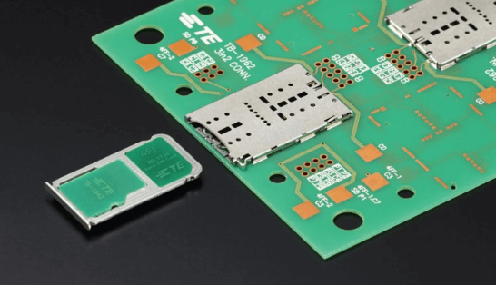
First, you should understand the technical requirements of your application to find the right connector. These parameters include: pin pitch, soldering method, voltage rating, current rating, mating cycles, temperature range, board spacing, connector geometry, and solder tab hole diameter.
Based on these specifications, you can search the websites of connector manufacturers and distributors. However, if more detailed specifications or even a customer-specific design are required, you should contact the connector manufacturer directly.
The timing of this contact is also crucial. The earlier a user engages with the manufacturer in the development process, the greater the chance of using standardized or slightly modified connectors.
2.Appropriate Design-In Timing
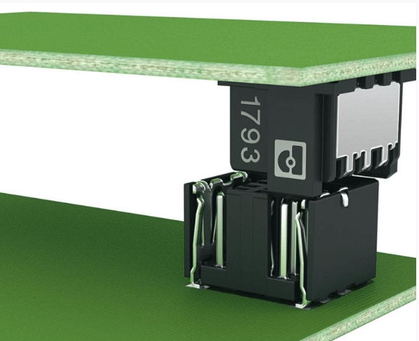
For many PCB designers, the placement of active components (such as microcontrollers, transistors, or diodes) plays a decisive role initially. Passive components such as capacitors, resistors, and even connectors are often relegated to later stages of the development process. However, this approach significantly increases the potential for conflicts.
For Your Next Connector Design-In: Considering Active and Passive Components Together
Failure to consider passive components during development can, in many cases, significantly increase PCB design complexity and costs. This is because, ultimately, it’s often no longer possible to use standard connectors; customer-specific connectors must be developed first.
For manufacturers, customer-specific connectors often require adjustments to production equipment or the production of customer-specific components and tools. Depending on the degree of customization, this can increase costs by anywhere from a few hundred to tens of thousands of dollars or euros.
However, for prototype quantities, these tooling adjustments are not cost-effective. Therefore, it’s crucial to consider connectors and all other passive components during the development process. Ultimately, customer project profit margins must be maintained.
3.Appropriate Packaging
In addition to the standardized cartons typically used for THT connectors, packaging is also available for automated assembly. Packaging options include tape and reel and cartridges. Cartons are typically used in the prototype phase or for low-volume production. Tape and reel packaging, on the other hand, is more likely to be used in mass production and, therefore, can be used for higher quantities.
In most cases, the maximum length of cartridges is approximately 500 mm. Tape and reel packaging is determined by the height of the connectors and the distance between the components on the conveyor. This means that more connectors can be transported and assembled on PCBs using tape and reel packaging.
4.Supply Chain
Many PCB connector manufacturers are located in the Far East. Due to current raw material shortages and long delivery times, there are significant opportunities for smaller European manufacturers. Many PCB assemblers and developers are currently seeking alternative connectors from the Far East through online material substitution.
However, users should consider quality differences, such as gold plating. While flash gold plating with a very thin layer is often used in the Far East, European electroplating companies typically use a minimum gold layer thickness of 0.2 µm.
Going forward, delivery delays can be eliminated by strengthening the US production base and sourcing suppliers in North America: for example, combining the 7-530671-2 (connector edge dual female 20POS 0.125) with the 583859-9 (connector card edge HSG 20POS 0.156 BLK) from TE Connectivity AMP Connectors, both of which are US-origin.
To this end, DigiKey not only reduces lead times but also offers a high level of expertise and quality that meets standard requirements and can assist in developing custom solutions.
5.Partners
The final tip is to choose a reliable partner with a long-term relationship. The manufacturer should not only reliably provide high-quality products but also offer the right combination of connector materials. For connector partners, the connector coating should be of the same material type, if possible.
Combining tin-plated pin connectors with gold-plated socket connectors is feasible, but it is detrimental to extending system life due to connector corrosion (electrochemical voltage range). In any case, it is best to use only tin-plated or pure gold connectors in your application.
The Magic Triangle of Cost, Time, and Performance
Customers have considerable freedom in selecting the appropriate PCB connector and packaging options. However, the magic triangle of cost, time, and performance plays a crucial role.
Currently, connectors from the United States and Europe are most likely to meet this magic triangle. This is because, in addition to short delivery times, they offer superior quality and a reasonable price structure.


